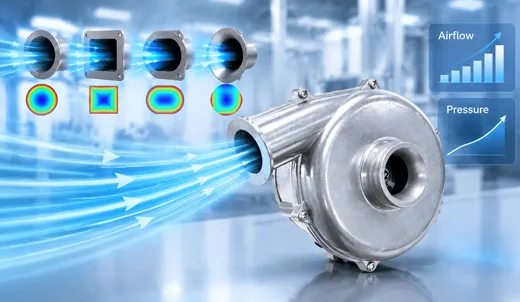

How to Design a Blower Outlet for Concentrated Airflow: A Practical Guide to 24V Air Blower Nozzle Engineering
Learn how outlet geometry, nozzle area, static pressure, airflow velocity, and system resistance work together to produce a focused air jet. This engineering guide explains the calculations, design considerations, and practical testing methods engineers can use when integrating a 24V air blower into industrial equipment.
Engineering Summary
- A concentrated air jet depends on outlet geometry, available pressure, actual operating airflow, and the distance to the target.
- The continuity equation, Q = A × V, provides a useful first estimate of average outlet velocity.
- Theoretical velocity calculated from static pressure is an idealized limit, not a guaranteed nozzle performance value.
- A blower and nozzle must be evaluated as one system using the manufacturer's pressure-flow curve.
- For repeatable results, validate airflow, target force, noise, temperature, and electrical power under real operating conditions.
1. Why Concentrated Airflow Matters in Industrial Applications
In industrial equipment, delivering air to the correct location can be just as important as generating a large volume of air. Applications such as PCB drying, electronic component cooling, motor cooling, surface cleaning, liquid removal, and automated production-line cleaning often require a controlled stream of air rather than a broad, rapidly dispersing flow.
A 24V air blower can provide a compact source of pressurized airflow for these applications. However, the final performance at the target depends on more than the blower's rated airflow. The outlet, connecting duct, bends, filters, protective grilles, and target distance all influence how much useful momentum reaches the workpiece.
For example, a wide outlet may cover a large surface uniformly, making it suitable for sheet drying or broad cooling. A narrow outlet may produce a smaller, more concentrated stream that is useful for removing droplets or directing air toward a specific component. Neither design is universally better; the correct choice depends on the required coverage, blowing force, working distance, and allowable noise.
Concentrated airflow should therefore be treated as a system-design objective. Increasing outlet velocity without checking pressure losses can reduce actual airflow, raise noise, or move the blower into an unsuitable operating region.
2. The Physics Behind a Concentrated Air Jet
2.1 The continuity equation: airflow, area, and velocity
For steady flow, the continuity equation relates volumetric airflow to the effective flow area and average air velocity:
Q = A × V
Q = volumetric airflow (m³/s)
A = effective outlet area (m²)
V = average air velocity (m/s)
Rearranging the equation gives V = Q/A. At a fixed actual airflow, reducing the outlet area increases the calculated average velocity. This is why a properly designed nozzle can create a faster, more focused jet than a large, unrestricted opening.
However, the phrase at a fixed actual airflow is essential. A centrifugal blower does not maintain its maximum free-air flow when the outlet is restricted. As nozzle resistance increases, the operating airflow changes according to the blower's pressure-flow characteristics and the resistance of the complete system.
Consequently, the continuity equation is a sizing tool, not proof that a smaller opening will always deliver a stronger jet. The real operating flow must be measured or determined from reliable performance data.
2.2 Bernoulli's principle and the pressure-velocity relationship
For an ideal, steady, incompressible flow along a streamline, Bernoulli's equation can be written as:
P + ½ρV² + ρgz = constant
P = static pressure (Pa)
ρ = air density (kg/m³)
V = air velocity (m/s)
g = gravitational acceleration (m/s²)
z = elevation (m)
When elevation changes are negligible, the relationship illustrates how pressure energy can be converted into kinetic energy. For an idealized pressure difference, an associated velocity estimate is:
Videal = √(2ΔP/ρ)
ΔP = usable pressure difference across the flow path (Pa)
At an illustrative air density of 1.225 kg/m³, a pressure difference of 7,890 Pa corresponds to an ideal velocity of approximately 113.5 m/s. This value is an idealized calculation, not a prediction that a particular 24V blower will produce a 113.5 m/s jet.
In a real installation, the available pressure must be evaluated at the actual operating point. Internal friction, inlet losses, bends, separation, leakage, compressibility, and outlet geometry affect the result. A blower's maximum static pressure and maximum airflow are generally measured at different operating conditions and must not be combined as if they occur simultaneously.
For further engineering background, consult the NASA Glenn Research Center's Bernoulli equation explanation. It provides a useful introduction to the relationship between pressure and velocity while highlighting the assumptions behind the ideal model.
3. Five Design Rules for a High-Performance Blower Outlet
Rule 1: Use a gradual contraction instead of an abrupt restriction
An abrupt reduction in duct area can cause local flow separation, recirculation, additional turbulence, and pressure loss. These effects reduce the amount of energy available for useful downstream airflow.
A gradual contraction can guide air toward the outlet with less abrupt directional change. Where the packaging allows, use smooth transitions, rounded internal corners, and a consistent passage without unnecessary steps. The contraction angle and length should be selected according to the inlet geometry, outlet area, available space, and required flow rate.
A contraction half-angle of approximately 15 degrees or less can serve as an initial geometry to investigate, but it is not a universal optimum. Short, high-resistance passages and low-Reynolds-number applications may require different proportions. Prototype measurements or computational fluid dynamics (CFD) can help determine whether a proposed geometry improves performance.
Rule 2: Select the outlet shape according to the target
Outlet geometry determines the shape and distribution of the emerging air jet. Common options include circular openings, rectangular slots, flat-fan outlets, and multi-channel nozzles.
- Circular outlets: Suitable for a compact, approximately round jet and localized cooling or cleaning.
- Rectangular slots: Useful for directing air across a line or narrow surface. Their aspect ratio influences the resulting flow distribution.
- Flat-fan outlets: Suitable for applications that require broad, relatively uniform surface coverage.
- Multi-channel outlets: Can divide the supply into several controlled jets and improve the overall flow pattern when appropriately designed.
A flat slot does not automatically create a perfectly collimated jet. Free jets spread as they travel, and rectangular jets can behave differently along their major and minor axes. The correct design should be assessed at the actual target distance rather than only at the nozzle exit.
Lechler's technical resource, Air Nozzles: Quiet and Efficient Solutions, describes flat-fan, round-jet, and multi-channel nozzle designs. Its industrial nozzle catalog reports that certain multi-channel nozzle designs can reduce sound levels by up to 12 dB compared with specified conventional single-hole nozzles. This is a product-specific comparison, not a guaranteed noise reduction for every blower-and-nozzle combination.
Rule 3: Keep the internal passage smooth and unobstructed
Surface roughness, molding flash, burrs, protruding fasteners, misaligned joints, and abrupt cross-sectional changes can create local losses. These details become particularly important when a compact blower operates at high rotational speed and the outlet has limited area.
Specify an internal finish appropriate to the manufacturing method and application. Injection-molded passages may be sufficient for many commercial designs, while demanding applications may benefit from improved tooling, carefully finished transitions, or a machined prototype.
Do not assume that the smoothest possible surface will always produce a measurable improvement. The effect depends on passage length, hydraulic diameter, Reynolds number, and the relative importance of friction versus local losses. Prioritize eliminating sharp discontinuities and unintended obstructions before spending heavily on polishing.
Rule 4: Match the nozzle to the blower's pressure-flow curve
A centrifugal blower has a pressure-flow, or P–Q, curve describing the pressure it can develop at different airflow rates under specified test conditions. The system also has a resistance curve determined by the inlet, outlet, ducts, filters, fittings, and nozzle.
The operating point occurs where the blower performance curve and system resistance curve intersect. Increasing nozzle restriction generally changes this intersection, so the actual flow can decrease even when the outlet velocity calculation suggests that a smaller opening should increase velocity.
This is why the maximum static pressure and maximum airflow shown in a product specification should be treated as separate limits. Neither value alone identifies the airflow that will be delivered through a particular nozzle.
Before finalizing the design, review the actual model's P–Q curve, confirm the test conditions, and assess the required flow at the expected system resistance. For additional guidance, read TKFAN's guide to why static pressure matters in air blower selection.
Rule 5: Design for the required working distance
A nozzle that produces a high exit velocity may not deliver the best performance several centimeters or meters downstream. The jet entrains surrounding air, spreads, and exchanges momentum with its surroundings. Its velocity profile changes with distance and outlet shape.
Define the target distance early in the design process. For example, a PCB cleaning nozzle positioned close to a board may require a narrow, carefully controlled stream, while an industrial drying station may need a wider air curtain with consistent coverage across the entire workpiece.
Evaluate the velocity distribution and useful blowing force at the target plane. A hot-wire anemometer, suitable airflow measurement instrument, or calibrated force measurement can help compare prototypes. Measure more than the centerline velocity: an extremely fast centerline surrounded by weak airflow may not meet a uniform-cleaning requirement.
4. Practical Calculation: Sizing a Slot for a TKFAN 24V Air Blower
Consider the TKFAN 24V air blower BA7050H24B as a representative engineering example. According to the TKFAN 24V air blower product range and the model's BA7050H24B product specification, the published values include 24 VDC operation, a rated speed of 37,000 rpm, maximum airflow of 17.8 CFM, and maximum static pressure of 7.89 kPa. The listed model dimensions are 70 × 66 × 45 mm.
Step 1: Convert the maximum airflow to SI units
Using 1 CFM ≈ 0.00047195 m³/s:
17.8 × 0.00047195 ≈ 0.00840 m³/s
This corresponds to approximately 8.40 L/s or 30.2 m³/h. It is the published maximum airflow, not necessarily the airflow available through the proposed nozzle.
Step 2: Calculate the area of a 50 mm × 5 mm slot
Suppose the preliminary design uses a rectangular opening that is 50 mm wide and 5 mm high:
A = 0.050 × 0.005
A = 0.00025 m²
Step 3: Calculate the idealized average velocity
If the maximum published airflow could pass through this area without changing, the continuity equation would give:
V = 0.00840 / 0.00025
V ≈ 33.6 m/s
Illustrative calculation only; not a measured or guaranteed operating velocity.
The calculation establishes a useful first-pass target, but it does not establish that the blower can deliver 8.40 L/s against the resistance of this slot. A 50 mm × 5 mm opening may impose a significant restriction, depending on the nozzle length, entrance shape, contraction, and discharge conditions.
Step 4: Check the pressure requirement and actual operating point
For an idealized velocity of 33.6 m/s and air density of 1.225 kg/m³, the associated dynamic pressure is:
q = ½ρV²
q ≈ 692 Pa
This is the ideal dynamic pressure associated with the assumed velocity. It is not the total pressure requirement of the real nozzle assembly. Actual losses and the flow pattern must be included, and the blower's maximum static pressure cannot simply be treated as a pressure budget that is entirely available at maximum airflow.
The correct next step is to use the manufacturer's P–Q curve and the nozzle's resistance characteristics to estimate the real operating airflow. Then measure the exit velocity and target-plane performance in the assembled system. If the target is not met, adjust the slot dimensions, transition profile, or blower selection and test again.
5. Choosing the Right TKFAN 24V Air Blower
Different applications require different combinations of airflow, pressure, power, size, and control capability. A model with a higher maximum static pressure may be useful for a restrictive nozzle, but it is not automatically the most efficient option for every application.
| Model | Voltage | Rated speed | Max. airflow | Max. static pressure |
|---|---|---|---|---|
| BA5025H24B-A | 24 VDC | 38,000 rpm | 11.1 CFM | 4.81 kPa |
| BA5030H24B-A | 24 VDC | 28,000 rpm | 6.0 CFM | 2.90 kPa |
| BA7050H24B | 24 VDC | 37,000 rpm | 17.8 CFM | 7.89 kPa |
| BA7060H24B | 24 VDC | 36,000 rpm | 16.0 CFM | 7.40 kPa |
| BA8050H24B-A | 24 VDC | 45,000 rpm | 26.0 CFM | 13.3 kPa |
Important: The table summarizes published model specifications from the TKFAN 24V air blower product range. Confirm the latest individual model datasheet before design approval, because specifications and model variants may change. Maximum airflow and maximum static pressure represent different operating limits; they are not simultaneous performance values.
For compact electronic equipment, a smaller model may be sufficient when the system resistance is low. For a narrow cleaning nozzle or a longer duct, a higher-pressure model may be worth evaluating. For a wide drying outlet, the required airflow distribution and coverage may be more important than the maximum pressure rating alone.
Engineers should compare the complete P–Q curve, electrical input, motor-control requirements, allowable operating temperature, acoustic performance, installation dimensions, and expected duty cycle. The best model is the one that meets the target-plane performance requirement with an acceptable electrical and thermal margin.
6. Airflow Entrainment and the Coandă Effect
A moving air jet can entrain surrounding air through turbulent mixing. This process increases the total volume of moving air downstream, but it does not create additional energy. The entrained air gains momentum from the supplied jet, and the resulting velocity profile depends on the geometry and surrounding conditions.
The Coandă effect describes the tendency of a fluid jet to follow a nearby curved surface under suitable conditions. Some air-amplification products use carefully engineered profiles to combine a primary air supply with entrained ambient air. Such designs can be valuable when the application needs a wider or amplified flow pattern.
However, an amplification ratio published for a particular commercial air knife or amplifier should not be applied directly to an ordinary centrifugal blower nozzle. The result depends on the device geometry, supply conditions, measurement method, and definition of the amplification ratio.
For a custom TKFAN 24V air blower assembly, consider a curved lip or Coandă-style profile only when it supports the required application. Compare it with a conventional outlet at the same electrical input and target distance, measuring both airflow distribution and useful blowing force.
7. Noise, Vibration, and Thermal Considerations
Increasing jet velocity can increase aerodynamic noise. Abrupt contractions, separated flow, sharp edges, and resonant ducts may introduce additional noise beyond the sound produced by the blower itself. A smoother outlet can help, but acoustic performance must be verified on the complete assembly.
Noise measurements should specify the measurement distance, microphone position, background noise, blower speed, operating voltage, and nozzle configuration. Sound pressure level in dB(A) depends on the test environment, so measurements from different setups are not directly comparable unless their conditions are controlled.
Restriction also changes the blower's operating point and can affect motor current, temperature, vibration, and stability. Do not assume that every centrifugal blower will experience the same response to restriction. Check the manufacturer's operating limits and avoid conditions that cause excessive temperature rise, abnormal noise, unstable flow, or electrical overload.
For industrial equipment, verify the following during prototype testing:
- Air velocity and distribution at the target surface.
- Actual airflow through the complete outlet assembly.
- Static pressure at an appropriate measurement point.
- Input voltage, current, and electrical power.
- Noise and vibration at the intended operating condition.
- Blower temperature after thermal stabilization.
- Performance after repeated start-stop cycles, where applicable.
8. A Practical Validation Workflow for Engineers
A reliable outlet design process should combine calculation, simulation when justified, and physical testing. The following workflow provides a repeatable starting point.
- Define the target. Specify the surface, working distance, required coverage, cleaning or cooling objective, and acceptable noise level.
- Set the operating conditions. Record the supply voltage, expected temperature, duty cycle, inlet restrictions, duct routing, and available installation space.
- Choose a candidate blower. Review the model datasheet and P–Q curve. Do not select a model using only its maximum airflow or pressure.
- Calculate an initial outlet area. Use the continuity equation with a realistic estimate of operating airflow and a preliminary target velocity.
- Design the flow path. Minimize abrupt changes, remove unnecessary obstructions, and select a shape that suits the required air distribution.
- Estimate system resistance. Account for contractions, bends, passages, filters, and the outlet. Use suitable engineering calculations or CFD when complexity justifies it.
- Build and measure a prototype. Measure flow, pressure, velocity distribution, noise, electrical input, and temperature under repeatable conditions.
- Refine and document. Compare alternative outlet geometries, record test conditions, and confirm that the final assembly meets the actual application requirements.
This process is particularly useful when integrating a compact 24V air blower into automated machinery, electronics cooling systems, surface-drying equipment, or targeted cleaning modules. It also provides a sound basis for discussing design requirements with a blower manufacturer.
9. Frequently Asked Technical Questions About 24V Air Blower Outlet Design
Q1. How can I make a 24V air blower produce a more concentrated airflow?
Start by selecting an outlet shape that matches the target, then optimize the contraction, internal transitions, and outlet area. Check the actual operating airflow and measure the velocity distribution at the working distance. A smaller opening alone does not guarantee better performance because added resistance can reduce total airflow.
Q2. Does a smaller blower outlet always increase air velocity?
Not necessarily. At a fixed volumetric flow rate, the continuity equation predicts higher average velocity when area decreases. In an actual blower system, however, the smaller opening increases resistance and may reduce the operating flow. Both effects must be evaluated together.
Q3. What is the difference between maximum airflow and maximum static pressure?
Maximum airflow is generally measured under a low-resistance or free-delivery condition, while maximum static pressure is generally measured near zero flow. These are different endpoints of the performance curve. The airflow available at a particular nozzle restriction must be determined from the P–Q curve and system resistance.
Q4. How do I calculate the outlet velocity of a TKFAN 24V air blower?
Use V = Q/A, with Q expressed in cubic meters per second and A in square meters. The critical step is using the actual airflow through the assembled system rather than automatically substituting the product's maximum free-air flow. Validate the calculated result with a suitable measurement instrument.
Q5. Is a rectangular slot better than a circular nozzle?
A rectangular slot is often useful for line-shaped airflow or surface coverage, while a circular nozzle can suit localized cooling or cleaning. The best option depends on target geometry, working distance, flow uniformity, pressure loss, and noise. Prototype testing determines which configuration performs better for the specific application.
Q6. How much pressure is required to generate a high-speed air jet?
The ideal relationship V = √(2ΔP/ρ) can estimate the pressure difference associated with a target velocity. Real designs also require consideration of inlet conditions, passage losses, discharge behavior, and compressibility. The blower must provide the required pressure at the actual operating flow, not merely list a high maximum static pressure.
Q7. Can a Coandă-style outlet improve concentrated airflow?
A properly designed Coandă-style profile can guide a jet along a curved surface and encourage entrainment of surrounding air. Whether it improves useful blowing force or coverage depends on geometry and operating conditions. Commercial air-amplification ratios should not be assumed to apply to a custom blower nozzle without testing.
Q8. How can I reduce noise from a high-speed blower outlet?
Investigate abrupt contractions, sharp edges, internal obstructions, duct resonance, and unnecessary turbulence. Compare smoother transitions and alternative nozzle geometries while maintaining the required target-plane performance. Measure sound pressure under controlled conditions because noise reduction depends on the complete system and measurement setup.
Q9. Which TKFAN 24V air blower model is suitable for a narrow, high-pressure nozzle?
The BA7050H24B and BA8050H24B-A are possible candidates to evaluate because their published maximum static pressures are 7.89 kPa and 13.3 kPa, respectively. These figures alone do not establish suitability. Compare their complete P–Q curves, electrical input, installation requirements, and required operating airflow before choosing a model.
Q10. What information should I provide when requesting a custom blower and nozzle solution?
Provide the required voltage, target airflow or velocity, nozzle dimensions, working distance, available space, duct layout, operating temperature, duty cycle, noise limits, and application environment. Include a drawing or CAD model when possible. These details help engineers evaluate the blower, outlet geometry, and expected operating point as one integrated system.
10. Conclusion: Optimize the Complete Airflow System
Designing a concentrated air jet requires more than reducing the outlet diameter. The most reliable approach combines basic fluid mechanics with careful blower selection, controlled outlet geometry, and repeatable validation.
Use the continuity equation to estimate the relationship between airflow, outlet area, and velocity. Use pressure-flow data to determine whether the selected 24V air blower can support the required operating point. Design smooth transitions, choose the outlet shape according to the target, and measure performance at the actual working distance.
For applications that need compact dimensions, controlled airflow, and meaningful static pressure, the TKFAN 24V air blower range provides several models for engineering evaluation. The BA7050H24B and BA8050H24B-A are two examples with different published airflow and pressure limits. Final selection should be based on the manufacturer's current data and the requirements of the complete system.
Explore the TKFAN 24V air blower product range to compare available models and identify a suitable starting point for your project. For application-specific support, provide the required airflow, pressure, outlet dimensions, and working distance so that the blower and nozzle can be evaluated together.
Technical References and Further Reading
1. TKFAN — 24V Air Blower Product Range. Manufacturer-listed model specifications and product selection information.
https://www.tkfan.com/products/airblower/24v-air-blower.html
2. TKFAN — BA7050H24B Product Specification. Model-specific voltage, speed, maximum airflow, maximum static pressure, and dimensions.
https://www.tkfan.com/products/airblower/24v-air-blower/ba7050h24b.html
3. TKFAN — Why Static Pressure Matters in Air Blower Selection. Related guidance on pressure requirements and blower selection.
https://www.tkfan.com/news/why-static-pressure-matters-in-air-blower-selection.html
4. NASA Glenn Research Center — Bernoulli Equation. Educational background on the relationship between pressure, velocity, and elevation in idealized fluid flow.
https://www.grc.nasa.gov/www/k-12/airplane/bern.html
5. Lechler — Air Nozzles: Quiet and Efficient Solutions. Technical overview of flat-fan, round-jet, and multi-channel air nozzle designs.
https://www.lechlerusa.com/en/products/product-by-type/air-nozzles
6. Lechler — Industrial Catalog. Technical examples and comparative performance information for selected industrial nozzle designs.
https://www.lechlerusa.com/fileadmin/media-usa/Literature/Catalog/CATALOG_501.pdf
Engineering note: Numerical examples in this article are illustrative calculations, not independent laboratory test results. Manufacturer-listed maximum values are not necessarily simultaneous operating values. Always verify the current model datasheet, P–Q curve, system resistance, and measured performance before releasing a design for production.
GET A QUOTE