

How the Geometric Shape of the Blower Inlet Affects Airflow and Pressure
An Engineering Analysis on Optimizing TKFAN Air Blower Performance for Maximum Efficiency and Pressure Recovery
1. Introduction: The Hidden Factor in Fluid System Design
In modern industrial ventilation, energy storage thermal management, medical apparatus, and precision automation, the air blower serves as the beating heart of the fluid management system. When system engineers select equipment, they typically prioritize rated airflow, static pressure curves, and motor power ratings. However, a critical mechanical detail is frequently overlooked: the geometric profile of the blower inlet.
It is common for an air blower to meet all laboratory datasheet specifications, only to experience a drastic drop in actual airflow and output pressure once integrated into an assembly. The root cause is rarely an impeller defect or motor failure; instead, it is improper inlet geometry design. As the transitional boundary where air converges from a resting ambient space into the restricted impeller channels, the inlet profile dictates flow smoothness, vortex formation, and energy loss levels.
Even with identical impellers and motor configurations, modifying the inlet contour of an air blower induces profound shifts in volumetric flow rate, static pressure, acoustic emission, and operating efficiency. Through years of rigorous research and testing across diverse industrial applications, the TKFAN engineering team has established that inlet geometry is the single most cost-effective yet undervalued parameter for elevating system performance. Optimizing inlet architecture eliminates pressure losses and boosts effective output without necessitating high-wattage motor upgrades. Discover our full selection of high-performance models by visiting the TKFAN air blower product lineup.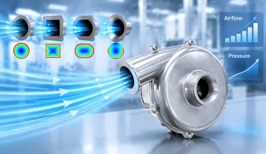
2. Fundamental Fluid Mechanics of Blower Inlets
Air behaves as a viscous fluid. When drawn from a stationary ambient environment into the internal architecture of an air blower, the local flow field undergoes intense acceleration. Air must transition rapidly from a large, stagnant volume into a narrow, rotating impeller eye. This convergence zone is governed by fluid acceleration, pressure transformation, and boundary layer development.
Bernoulli's principle underpins this phenomenon: in a steady, incompressible flow field (where air behaves as incompressible under low-pressure, low-speed conditions), total pressure equals the sum of static pressure and dynamic pressure. As the inlet passage contracts, air velocity (dynamic pressure) surges, causing a corresponding drop in static pressure. If the inlet profile features sharp or abrupt transitions, the fluid boundary layer detaches from the solid walls, generating turbulent eddies that dissipate energy and cause irreversible pressure losses.
The boundary layer is a thin veneer of low-velocity air adhering to the interior wall. Ideally, this layer remains attached, flowing smoothly along the contour. Sharp edges or sudden geometry shifts trigger boundary layer separation, creating expansive vortex zones that consume blower power while generating mechanical vibration and elevated noise. The primary objective of advanced inlet geometry design is to guide airflow through smooth, continuous contraction, delay boundary layer separation, minimize entry losses, and ensure uniform velocity distribution across the impeller blades.
3. Detailed Breakdown of Inlet Geometries and Their Fluid Impacts
3.1 Straight-Tube Inlets (Sharp-Edged Orifice)
The straight-tube sharp-edged inlet is the simplest and most inexpensive configuration, commonly utilized in economy-grade air blowers. The entrance features a 90-degree square corner with zero radius transition.
When air approaches a sharp edge, it cannot smoothly negotiate the right angle. Consequently, the air stream contracts immediately past the entrance, forming a vena contracta where the effective flow area shrinks below the physical duct diameter. Intense vortices concentrate directly inside the sharp corner, driving local resistance coefficients sky-high.
- High Pressure Loss: Resistance coefficients hover around 0.5, representing the highest energy dissipation among inlet types. Much of the static pressure is squandered at the threshold.
- Uneven Flow Distribution: Impeller blades experience skewed, non-uniform air loading, triggering mechanical vibration and elevated acoustic signatures.
- Severe Airflow Suppression: Under high-pressure loads, vortex choking exacerbates performance degradation, causing actual flow rates to fall far short of nominal ratings.
3.2 Bell Mouth Inlets (Bell-Shaped Convergent Nozzles)
The bell mouth inlet represents the gold standard for high-performance fluid handling. Featuring a smooth, mathematically optimized curved contour, it gradually transitions from a wide outer diameter down to the impeller inlet eye. Many high-efficiency TKFAN air blower models incorporate this superior aerodynamic profile as standard equipment.
The contoured bell mouth guides air smoothly along the interior walls, ensuring the boundary layer remains fully attached with zero separation zones. Air enters the impeller blade matrix with uniform velocity vectors.
- Minimal Pressure Loss: Resistance coefficients drop as low as 0.05 to 0.1, cutting entry pressure losses by over 80% compared to sharp-edged tubes and maximizing system static pressure.
- Stable Velocity Profiles: Balanced aerodynamic loading across the entire impeller face unlocks the full rated capacity of the air blower.
- Extended Operating Range: Surge margins are significantly enhanced, allowing stable operation across a wider flow spectrum.
3.3 Conical Convergent Inlets
Conical inlets utilize straight angular sloping walls to achieve contraction—a middle-ground compromise between sharp tubes and smooth bell mouths. The taper angle dictates overall aerodynamic efficiency.
When taper angles remain narrow (under 15 degrees), flow remains orderly with minimal loss. However, angles exceeding 30 degrees trigger boundary layer detachment at the terminal end, causing vortex regeneration and sudden pressure spikes.
3.4 Rounded-Edge Inlets
Rounded-edge inlets introduce a simple radius fillet onto a standard straight tube. As an economical upgrade, the radius-to-diameter ratio ($R/D$) dictates performance. Industry best practice recommends a radius of at least 10% of the inner pipe diameter to yield measurable improvements, cutting resistance coefficients down to 0.2–0.4.
3.5 Venturi-Style Composite Inlets
Venturi structures feature a complex converging-diverging profile that leverages the Venturi effect to actively regulate velocity and pressure. While demanding extreme manufacturing precision, a well-calibrated Venturi inlet recovers dynamic pressure and converts it into static pressure head, serving specialized medical and precision industrial applications.
4. Fluid Losses: Separation, Vortices, and Pressure Drops
The primary mechanism of inlet inefficiency is flow separation. When local surface curvature changes abruptly, the kinetic energy within the boundary layer becomes insufficient to overcome adverse pressure gradients. The fluid breaks away from solid boundaries, creating stagnant recirculation zones.
Within these vortex pockets, kinetic energy degrades into unrecoverable thermal energy. This wasted power prevents the air blower from delivering its designed pressure and flow. Furthermore, intermittent vortex shedding induces periodic pressure pulsations that translate into structural vibration, acoustic noise, and localized blade stress fatigue.
5. Impact on Blower Performance Curves
Blower characteristic curves chart the relationship between flow rate, static pressure, efficiency, and noise. Inlet geometry directly reshapes these operational boundaries:
- Maximum Static Pressure: Severe entry losses truncate maximum achievable pressure, whereas optimized bell-mouth inlets shift the entire pressure curve upward.
- Peak Efficiency Sweet Spot: Mitigating entrance friction broadens the high-efficiency operating window.
- Surge Suppression: Clean inlet flow dampens turbulence, narrowing unstable operating zones at low flow rates.
6. Industrial Selection Guide for TKFAN Air Blowers
Choosing the correct equipment requires evaluating environmental constraints, system resistance, and aerodynamic profiles in tandem. Explore our full catalog at TKFAN air blower to find matching configurations tailored to your specifications:
- High-Pressure & Precision Medical Devices (CPAP, Gas Analyzers): Select bell-mouth inlet configurations to ensure low acoustic signatures and precise flow control.
- Standard Enclosure Cooling: Utilize conical convergent models for an optimal balance of cost-effectiveness and performance.
- Space-Constrained Retrofits: Deploy rounded-edge inlet designs to secure performance gains without structural overhauls.
7. Common Misconceptions Regarding Blower Inlets
Myth 1: Larger inlet diameter guarantees higher airflow. False. Without smooth transitional contours, oversized square edges generate massive contraction zones and choking vortices.
Myth 2: Inlet shape affects pressure only, not volumetric flow. False. Pressure losses increase effective system resistance, forcing the operating point down and reducing delivered volume.
Myth 3: Catalog ratings reflect real-world performance regardless of ducting. False. Laboratory tests assume pristine, unobstructed inlet conditions that are rarely replicated in tight field installations without proper engineering.
8. Conclusion
The inlet geometry of an air blower governs the initial entry, boundary layer stability, and total energy efficiency of the fluid system. Whether deploying economic straight tubes or advanced bell-mouth convergent nozzles, understanding these principles prevents costly performance shortfalls. For robust cooling, medical, and industrial solutions, integrate precision-engineered components from the TKFAN air blower collection into your next engineering project.
9. Frequently Asked Questions (FAQ)
Q1: How much does inlet geometry affect air blower noise levels?
A1: Significantly. Sharp-edged entries create continuous shedding vortices that generate heavy aerodynamic noise. Upgrading to a smooth bell-mouth inlet can reduce overall operating noise by 3 to 8 decibels under equivalent flow conditions.
Q2: Can I retrofit a bell-mouth inlet onto an already purchased air blower?
A2: Yes. Adding a matching external bell-mouth collector to the intake is a highly effective field optimization technique, provided it aligns coaxially and seals securely without air leaks.
Q3: Do inlet shapes impact high-pressure blowers and low-pressure air blowers differently?
A3: High-pressure blowers are far more sensitive due to elevated fluid velocities and stronger boundary layer reactions, though low-pressure systems also secure measurable efficiency gains.
Q4: How does inlet duct length interact with inlet geometry?
A4: Inlet duct length introduces cumulative friction drag (line losses) that compounds with local entry turbulence (local losses), requiring both factors to be evaluated together during system design.
Q5: What is the optimal radius-to-diameter ratio for a rounded inlet?
A5: Industry standards recommend an $R/D$ ratio of at least 0.1 to 0.15 to effectively eliminate separation zones while keeping manufacturing complexity manageable.
Q6: Does ambient temperature affect inlet performance efficiency?
A6: Indirectly. Temperature changes fluid density and viscosity, altering Reynolds numbers and shifting boundary layer stability slightly near the inlet boundary.
Q7: Why do some blowers feature asymmetrical intake housings?
A7: Asymmetrical housings are typically dictated by tight enclosure layouts, though engineers must carefully manage pre-swirl effects to prevent localized performance drop-offs.
Q8: Can computational fluid dynamics (CFD) accurately predict inlet losses?
A8: Yes, modern CFD simulation tools accurately model boundary layer separation and turbulence eddy dissipation, allowing engineers to prototype optimal inlet contours digitally.
Q9: How do inlet screens or filters influence air blower intake efficiency?
A9: Protective screens introduce pressure drops; if placed too close to the inlet edge, they disrupt uniform flow convergence and interact negatively with poor inlet geometries.
Q10: Where can I find official technical drawings for TKFAN air blower inlets?
A10: Detailed CAD models and specification sheets are available directly through the TKFAN air blower product pages.
GET A QUOTE