

Can a Blower Deliver High Pressure, High Speed and High Airflow Simultaneously?
1. Introduction: Common Misconceptions Among OEM Design Engineers
Every mechanical engineer, thermal design specialist, and component procurement manager sourcing DC centrifugal air movers encounters a fundamental question during product development: Can a blower deliver high pressure, high speed, and high airflow simultaneously under the exact same operating point?
In original equipment manufacturer (OEM) design workflows, a pervasive misconception exists: many assume that simply pairing a high-speed brushless DC (BLDC) motor with a high-rpm impeller will immediately unlock peak static pressure and maximum volumetric airflow at the same time. R&D personnel frequently review datasheets for a high pressure blower and examine three isolated peak metrics: maximum rotational speed (RPM), maximum static pressure (kPa or inH₂O), and maximum free-air volumetric flow rate (CFM). They then incorrectly assume these three absolute maximums can be achieved concurrently inside an enclosed equipment chassis.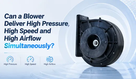
This erroneous assumption leads to failed prototype testing, thermal throttling, unexpected stall noise, and costly project delays. The truth is governed by immutable physics: fluid dynamics, BLDC motor thermal constraints, aerodynamic blade stall limits, and the classic Fan Affinity Laws enforce strict engineering trade-offs. While modern engineered air movers—such as the optimized TKFAN high pressure blower product line—can achieve exceptional balanced performance at a realistic system operating point, no blower can simultaneously deliver its standalone datasheet peak values for pressure, speed, and airflow at a single moment.
2. Core Definitions: High Pressure Blower, High Speed Blower, and High Airflow Blower
Before evaluating performance trade-offs, we must establish precise definitions for the three distinct performance classifications used across the compact industrial DC blower industry.
High Pressure Blower
A high pressure blower is a centrifugal turbomachine explicitly engineered to generate high static pressure rise to overcome significant system impedance (resistance). Common sources of high system resistance include dense HEPA filters, narrow internal air ducts, long piping networks, micro-diameter nozzles, and densely packed electronic enclosures. Static pressure is measured in kilopascals (kPa), inches of water gauge (inH₂O), or millimeters of water gauge (mmH₂O). Compact industrial DC high-pressure blowers typically operate within a pressure range of 2.9 kPa to 24 kPa or higher. Unlike axial cooling fans, a high pressure blower converts rotational kinetic energy into static pressure potential energy within its volute housing, driving air forcefully through high-restriction pathways.
High Speed Blower
A high speed blower is defined by an impeller operating at rotational speeds significantly exceeding standard cooling fan limits. Compact industrial DC high-speed blowers typically feature BLDC motors spinning between 25,000 RPM and 48,000 RPM (or beyond). Elevating the impeller tip speed is the primary engineering method used by manufacturers to boost static pressure output in compact footprints. However, running a high speed blower introduces intrinsic physical trade-offs: power consumption escalates dramatically, motor winding temperatures rise, bearing fatigue stress accelerates, and acoustic noise increases.
High Airflow Blower
A high airflow blower prioritizes volumetric air delivery, measured in cubic feet per minute (CFM) or cubic meters per hour (m³/h). High airflow blowers excel in low-impedance scenarios such as open-cabinet ventilation, large-area convective cooling, and free-air circulation. Engineers frequently overlook a critical caveat: any datasheet value for maximum CFM in a high airflow blower is measured under laboratory zero-backpressure conditions (Free Air). As soon as internal chassis resistance is introduced, actual delivered airflow drops sharply, regardless of how optimized the unit is for high volume flow.
| Classification | Core Metric | Typical Compact DC Range | Primary Engineering Target |
|---|---|---|---|
| High Pressure Blower | Max Static Pressure (kPa) | 2.9 kPa – 24.0+ kPa | Overcoming heavy system resistance (HEPA filters, dense ducts, nozzles) |
| High Speed Blower | Rotational Speed (RPM) | 25,000 – 48,000+ RPM | Maximizing impeller tip speed to generate high pressure potential |
| High Airflow Blower | Volumetric Airflow (CFM) | 6.0 – 72.4+ CFM | Moving large air volumes across low-impedance open environments |
3. The Fan Affinity Laws: Underlying Physical Principles Governing Performance
All centrifugal blowers strictly obey the Fan Affinity Laws, derived from Euler's turbomachinery equations. These laws describe how performance variables change when the rotational speed (RPM) of an impeller of fixed geometry is altered:
- Airflow (CFM) is directly proportional to speed: \( Q_2 = Q_1 \times \left(\frac{RPM_2}{RPM_1}\right) \)
- Static Pressure (kPa) is proportional to the square of speed: \( P_2 = P_1 \times \left(\frac{RPM_2}{RPM_1}\right)^2 \)
- Power Input (Watts) is proportional to the cube of speed: \( W_2 = W_1 \times \left(\frac{RPM_2}{RPM_1}\right)^3 \)
This mathematical relationship reveals the primary engineering bottleneck. While increasing the rotational speed of a high speed blower raises its theoretical maximum pressure and airflow capacity, power consumption increases exponentially by a factor of three. Inside a compact high pressure blower, physical space for BLDC copper motor windings, magnets, and heat dissipation is limited. Electrical power consumption and winding heat quickly hit safe thermal ceilings, preventing infinite speed scaling.
Furthermore, affinity calculations yield theoretical laboratory peak boundaries. In real equipment, system impedance creates an operational intersection known as the system operating point. When a high-pressure unit operates against high system resistance, its actual working CFM is only a fraction of the maximum free-air flow rated for a high airflow blower.
4. The P-Q Performance Curve: Why Three Peak Metrics Cannot Coexist at One Operating Point
Every centrifugal air mover is characterized by a Pressure-Volume (P-Q) performance curve, which plots static pressure output against volumetric airflow at a constant operating speed. The P-Q curve possesses two absolute boundary limits that are physically mutually exclusive:
1. Free Air Operating Point (Zero Backpressure)
At zero system resistance, the blower achieves its maximum rated CFM airflow—the peak capacity of a high airflow blower. However, static pressure output drops to absolute zero. Even if a high speed blower is driven to its maximum rated RPM, it cannot deliver static pressure under free-air conditions. This point is completely unsuitable for applications requiring air to pass through dense filters or restrictive nozzles.
2. Deadhead Operating Point (Maximum Static Pressure)
At the opposite end of the P-Q curve, the blower reaches its maximum static pressure rating—the peak limit of a high pressure blower. At this shut-off point, volumetric airflow drops to zero. Even when spinning at maximum high speed blower RPM, holding high pressure against a blocked system starves the system of volumetric air exchange.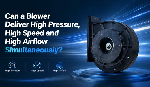
Between these two extremes lies the functional operating region. Within this stable region, a well-designed unit delivers strong pressure, elevated speed, and practical airflow, but it will never hit all three maximum datasheet values simultaneously.
Additional Physical Constraints:
- Motor Thermal & Power Density Limits: Pushing a high speed blower to maximum RPM while attempting to force high airflow against steep backpressure causes power consumption to spike. Excessive thermal buildup inside compact BLDC windings can cause magnet demagnetization, insulation breakdown, bearing grease failure, and premature motor burnout.
- Aerodynamic Blade Stall Limits: Operating near high static pressure without sufficient flow can push the impeller blades into aerodynamic stall. Aerodynamic stall generates turbulent backflow, pressure fluctuations, low-frequency acoustic hums, and severe structural vibration, which accelerates bearing wear and causes mechanical fatigue.
5. Real-World Hardware Benchmarks: Industrial DC Blower Performance Data
The following performance data from the TKFAN high pressure blower series illustrates the physical trade-offs inherent in compact centrifugal blower design across different sizing profiles.
| Model Number | Dimensions (mm) | Voltage (V) | Speed (RPM) | Max Airflow (CFM) | Max Pressure (kPa) | Design Optimization Focus |
|---|---|---|---|---|---|---|
| BA5025H24B-A | 50 × 50 × 25 | 24V | 38,000 | 11.1 | 4.8 | Ultra-compact high pressure blower for tight spaces |
| BA5030H12B-A | 58 × 50 × 28 | 12V | 39,100 | 8.6 | 6.15 | High-speed micro-blower for targeted pressure delivery |
| BA8050H24B-A | 80 × 50 | 24V | 45,000 | 25.9 | 13.4 | Balanced pressure-speed-airflow industrial profile |
| BA8060H24B-E | 86 × 82 × 60 | 24V | 48,000 | 25.1 | 18.2 | Extreme high speed blower with ultra-high pressure output |
| BA9080H24B-A | 103 × 86 × 76 | 24V | Lower Peak | 72.4 | 18.4 | High airflow blower profile with large volute volume |
Analyzing this empirical data confirms key turbomachinery design principles:
- Model BA8060H24B-E achieves an impressive speed of 48,000 RPM and generates 18.2 kPa of pressure, but its maximum airflow is capped at 25.1 CFM.
- Model BA9080H24B-A delivers an industry-leading 72.4 CFM of airflow due to its enlarged housing design, but it requires lower peak RPM to achieve its pressure profile.
- Model BA8050H24B-A serves as a versatile OEM solution, balancing high speed, pressure, and airflow without claiming impossible simultaneous peaks.
6. System Operating Point: Why Datasheet Peaks Mislead Field Calculations
A frequent error during blower selection is relying on three unlinked peak numbers: maximum RPM (high speed blower metric), maximum static pressure in kPa (high pressure blower metric), and maximum free-air CFM (high airflow blower metric). These numbers are measured under separate testing conditions and do not co-occur during actual operation.
Actual performance is dictated by the System Operating Point—the precise intersection between the blower's P-Q performance curve and the equipment's system impedance curve (\(P = C \times Q^2\)).
- In high-impedance applications (e.g., medical HEPA filtration), the operating point shifts left along the curve: static pressure increases, but actual CFM airflow decreases.
- In low-impedance applications (e.g., open cabinet cooling), the operating point shifts right: delivered CFM increases, but available static pressure drops near zero.
When selecting a high pressure blower, always request a complete P-Q curve mapped according to ISO 5801 or AMCA 210 standards from your manufacturer rather than relying solely on summary specification tables.
7. Engineering Risks of Forcing "Triple Peak" Expectations
Attempting to force an industrial air mover to simultaneously hit peak high pressure, peak high speed, and peak high airflow leads to several failure modes during field testing or mass production:
- Motor Thermal Overload and Burnout: Forcing a high speed blower to operate continuously outside its stable thermal window causes rapid heat accumulation in BLDC windings, leading to winding short circuits, magnet demagnetization, and permanent failure.
- Aerodynamic Stall and Severe Vibration: Operating near deadhead static pressure triggers blade stall, causing low-frequency noise, pressure fluctuations, and mechanical vibration that can loosen fasteners and damage bearings.
- Discrepancies Between Prototypes and Specifications: Designing a system based on free-air CFM while requiring high static pressure results in inadequate airflow during prototype testing, forcing costly engineering revisions.
- Excessive Acoustic Noise: Operating near physical limits significantly increases aerodynamic shear noise and structural vibration, causing equipment to exceed regulatory noise limits.
8. Practical Optimization Strategies Within Physical Limitations
While an air mover cannot deliver all three peak metrics simultaneously, engineers can optimize system performance by applying these best practices:
- Identify the True System Operating Point First: Calculate system resistance before choosing a blower. Map your required pressure and airflow targets to the center of a candidate blower's P-Q curve, avoiding deadhead and free-air limits.
- Upsize Frame Sizing Instead of Simply Elevating RPM: Rather than driving a small high speed blower to extreme RPMs, choose a slightly larger unit when space permits. Larger impellers generate equivalent pressure and airflow at lower speeds, reducing power draw, heat, and acoustic noise.
- Design System Ducting to Minimize Impedance: Smooth sharp bends, reduce tight constrictions, and select appropriate filter surface areas to lower system resistance. Shifting the operating point to the right yields higher airflow without requiring higher motor speeds.
- Request Customized Aerodynamic Tuning: Manufacturers like TKFAN can customize blade angles, volute geometries, and motor drive firmware to optimize performance specifically around your target operating point.
- Implement Closed-Loop Speed and Thermal Control: Use PWM control with tachometer feedback and thermal monitoring to dynamically adjust blower speed based on real-time cooling demands, protecting the motor from thermal stress.
9. Typical Industrial and OEM Application Scenarios
Understanding these trade-offs helps design teams choose the right blower profile for demanding applications:
- Autonomous Vehicle Sensor Cleaning Systems: Compact high speed blowers deliver high static pressure to blast dust and water droplets off camera lenses and LiDAR sensors through narrow nozzles.
- Medical Ventilation and CPAP Devices: High pressure blowers deliver precise airflow against breathing circuit resistance while maintaining low noise levels and rapid dynamic response.
- Pneumatic Conveying and Aeration Systems: Industrial blowers push granular materials or supply underwater aeration, requiring sustained static pressure capacity.
- Commercial Kitchen and Air Purification Equipment: Compact blowers overcome dense grease or carbon filters to ensure consistent air filtration.
- Dense Electronics and Server Cooling: High pressure blowers force cooling air through packed server chassis and power electronics enclosures.
10. Frequently Asked Questions (Technical FAQ)
11. Conclusion for Hardware Designers and Sourcing Professionals
To address the original question: a single industrial blower cannot simultaneously deliver its standalone peak maximum static pressure, maximum high speed, and maximum free-air airflow at one single operating point due to fundamental fluid dynamics and thermodynamic principles.
However, modern high-performance air movers—such as the TKFAN high pressure blower series—offer exceptionally balanced performance profiles that deliver high static pressure capacity, high motor speeds, and practical airflow rates across real-world system impedance ranges.
Successful engineering design requires identifying your actual system operating point, evaluating full P-Q curves, and collaborating early with blower specialists to customize aerodynamic settings for long-term operational reliability.