

High Airflow vs High Pressure: Core Performance Differences of High-Speed Centrifugal Fans
Introduction: The Engineering Dilemma in Compact Thermal & Fluid Systems
Modern miniature electronic, medical, and industrial systems rely heavily on high-speed centrifugal fans (often referred to as high-speed centrifugal blowers) to solve conflicting thermal management, ventilation, and dynamic air-delivery challenges. Whether designing a life-critical medical ventilator, a Powered Air-Purifying Respirator (PAPR), a CPAP machine for sleep apnea, a high-acceleration 3D printer, a high-density server rack, or an automotive electronic control unit (ECU), engineers face a fundamental aerodynamic trade-off: Should the system prioritize high airflow or high pressure?
A significant portion of early-stage prototyping failures stems from a misunderstanding of how airflow—measured in Cubic Feet per Minute (CFM) or Liters per Minute (L/min)—and static pressure—measured in Kilopascals (kPa) or Pascals (Pa)—interact inside a high-speed micro centrifugal blower. Operating at speeds up to 100,000 RPM, these miniature brushless DC (BLDC) blowers convert rotational mechanical energy into fluid momentum using low-inertia impellers housing specialized volute geometries. However, across any fan performance curve (P-Q curve), pressure and airflow exist in an inverse relationship: as system impedance increases, delivered volumetric airflow drops.
This technical guide provides a deep mechanical and aerodynamic breakdown of high airflow versus high pressure high-speed centrifugal fans. It details structural design variations, fluid dynamics principles, application boundaries, common engineering pitfalls, and step-by-step OEM/ODM selection workflows. Understanding these parameters ensures optimal product reliability, acoustic management, energy efficiency, and operational safety in high-density thermal and medical applications.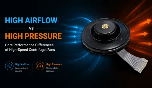
Defining Airflow (CFM) vs. Static Pressure (kPa) in High-Speed Blowers
What Is Airflow (CFM)?
Airflow represents the total volumetric rate of air moved by the centrifugal fan per unit of time, typically quantified in CFM or L/min. In high-speed centrifugal fans, maximum airflow defines the blower's capability under open-air (zero static pressure or zero impedance) operating conditions.
Blowers optimized for high airflow deliver large volumes of gas in systems featuring low aerodynamic resistance. Examples include straight short ventilation ducts, open chassis cooling, unrestrictive heat sinks with wide fin spacing, and enclosure air exchange. Mechanically, maximizing free-air CFM requires larger inlet diameters, wider blade pass channels, and expanded volute housing geometries. However, published maximum CFM figures are measured in unrestricted test chambers. When a high-airflow fan encounters system resistance—such as HEPA filters, micro-bore tubing, sharp elbows, or dense heat sinks—the actual delivered airflow drops sharply, regardless of motor speed.
What Is Static Pressure (kPa)?
Static Pressure measures the potential energy generated by the blower to overcome systemic resistance (system impedance). It determines how effectively the centrifugal fan forces air through restrictive pathways while maintaining a required volumetric flow rate.
System resistance originates from high-efficiency particulate air (HEPA/ULPA) filters, narrow medical tubing, tortuous air channels, micro-channel heat sinks, tightly packed PCB enclosures, and small-diameter exhaust orifices. A high-pressure high-speed centrifugal fan relies on a logarithmic volute casing to convert dynamic velocity pressure into static pressure. As high-speed air leaves the blade tips, the expanding scroll housing decelerates the airflow, converting kinetic velocity into potential pressure energy.
Core Aerodynamic Trade-off: Within fixed envelope dimensions, motor power limits, and operating voltages, maximizing static pressure capability naturally reduces maximum free-air flow rate. Conversely, maximizing volumetric airflow limits peak static pressure generation. Achieving high levels of both simultaneously requires increasing physical frame size, scaling electrical power consumption, or raising operational RPM.
Internal Mechanical Design Differences: High Airflow vs. High Pressure
The performance profile of a high-speed centrifugal fan is dictated by three core mechanical components: blade geometry, volute casing configuration, and BLDC motor tuning. Manufacturer designs like TKFAN High-Speed Centrifugal Fan Series highlight these structural differences across specialized models.
1. Impeller & Blade Design Geometry
The impeller is the primary energy-transfer mechanism within a centrifugal blower.
- High Airflow Impellers: Designed with wider blade channels, larger inlet eyes (suction diameters), and moderate forward or backward blade curvature. This geometry increases intake volume capacity while maintaining lower blade loading, generating moderate static pressure in favor of high mass flow rates.
- High Pressure Impellers: Features narrower airflow channels, tight tip clearance relative to the volute wall, and aggressive blade angles (often forward-curved or radial-tipped). Narrower channels accelerate air to extreme tip speeds, building high static pressure at the cost of intake volume capacity. Medical-grade blowers for ventilators and PAPR systems utilize these compact, high-velocity impellers to push air past dense HEPA media and narrow patient circuits.
High-performance blowers utilize lightweight, low-inertia polymer impellers (such as medical-grade PBT or PC). Low rotational mass permits acceleration and deceleration within milliseconds—a critical requirement for dynamic pressure regulation in clinical ventilation.
2. Volute Housing & Expansion Profile
The volute scroll collects air exiting the impeller tips and converts kinetic energy into static pressure via diffusion.
- High Airflow Volute Housing: Utilizes a larger cross-sectional flow area and a wide discharge port. This minimizes internal flow friction, allowing large volumes of air to exit smoothly with minimal internal backpressure creation.
- High Pressure Volute Housing: Engineered with a tight expansion ratio, precise cut-off clearance (tongue spacing), and an engineered diffuser outlet section. The volute strictly controls flow expansion to decelerate air precisely, converting velocity pressure ($P_v = \frac{1}{2}\rho v^2$) into static pressure ($P_s$).
3. BLDC Motor Tuning & Control Electronics
Brushless DC motors drive high-speed centrifugal blowers up to 100,000 RPM, supported by specialized drive electronics.
- High Airflow Tuning: Motors are optimized for torque balance at mid-range RPMs to sustain continuous, energy-efficient high-CFM delivery without excessive thermal buildup.
- High Pressure Tuning: Motors are wound for high RPM limits and rapid transient response. They utilize high-temperature ceramic or dual-precision ball bearings paired with synthetic high-speed grease to withstand continuous thermal and mechanical stress. Integrated PWM (Pulse-Width Modulation) control and FG (Tachometer) feedback allow system controllers to ramp RPM dynamically when pressure drops are detected.
| Performance Metric / Design Vector | High Airflow Centrifugal Fans | High Pressure Centrifugal Fans |
|---|---|---|
| Primary Performance Goal | Maximum volumetric air movement (High CFM) | Maximum static pressure generation (High kPa / Pa) |
| Impeller Architecture | Wide blade channels, large inlet eye diameter | Narrow blade channels, tight tip clearances |
| Volute Housing Geometry | Large internal cross-section, wide outlet port | Precision progressive expansion scroll with diffuser section |
| Ideal System Impedance | Low resistance (< 0.2 kPa) | High resistance (0.5 kPa to 10+ kPa) |
| Aerodynamic Limitation | Airflow drops rapidly when backpressure rises | Lower peak CFM under unrestricted zero-pressure conditions |
| Acoustic Profile | Dominated by broadband aerodynamic air-shuffling noise | Higher blade pass frequency (BPF) and high-pitch tone at extreme RPM |
| Target Applications | Chassis ventilation, wide heat sinks, 3D printing enclosure air, open ducts | CPAP, ICU ventilators, PAPR respirators, HEPA filters, micro-channel coolers |
Application Selection: Choosing the Right Blower Profile
When to Select a High Airflow Centrifugal Fan
High airflow blowers are ideal for applications where systemic resistance is minimal and the primary objective is rapid heat exchange or air displacement:
- Open Electronics Chassis & Servers: Cools high-density PCBs where component placement leaves open air pathways and heat sink fin gaps are wide.
- Short-Duct Fresh Air & Ventilation Units: Moves large air volumes through short, straight ducting with minimal internal restriction.
- 3D Printer Enclosure Circulation: Maintains steady internal ambient temperatures in closed-loop printing chambers with unrestrictive filtration.
When to Select a High Pressure Centrifugal Fan
High pressure blowers are mandatory in systems featuring restrictive fluid networks, dense media, or required dynamic pressure delivery:
- Medical ICU Ventilators & CPAP Machines: Pushes breathing air through humidifiers, bacterial filters, flow sensors, and long, small-bore patient tubing. The blower must dynamically modulate static pressure in milliseconds to align with patient inhalation and exhalation cycles.
- Powered Air-Purifying Respirators (PAPR): Forces ambient air through high-density HEPA/ULPA filters to deliver safe breathing air into protective hoods or face masks. As dust collects on the filter, the fan must ramp pressure to maintain safe delivery flow rates.
- Micro-Channel Coolers & Automotive ECUs: Cools tightly packed automotive electronics, laser diodes, and projection systems where cooling channels are constricted and tortuous.
Common Engineering Pitfalls in Centrifugal Fan Selection
- Relying Solely on Published Maximum CFM: Data sheet max CFM is measured at zero backpressure. In a real system with filters and narrow ducts, operating flow rates depend entirely on the fan's P-Q curve at your specific system impedance point.
- Ignoring Dynamic Pressure Response in Medical Systems: Medical respiratory devices require fast dynamic response times. High impeller rotational inertia delays acceleration, leading to pressure lag during breathing cycles. Utilizing low-inertia impellers prevents this lag.
- Failing to Account for HEPA Filter Dust Loading: HEPA filters increase in static resistance as particulate matter accumulates. Selecting a blower that barely meets airflow requirements with a clean filter leads to premature system performance degradation as the filter loads over time. A 20%–30% static pressure safety margin is recommended.
- Expecting High CFM and High kPa from a Compact Frame: Airflow and static pressure are bound by fluid mechanics laws. To increase both without enlarging fan dimensions, engineers must account for higher power draw, elevated operating RPM, and potential acoustic increase.
Step-by-Step Blower Selection Workflow for OEMs/ODMs
- Calculate Required Operational Flow Rate ($Q_{target}$): Determine the actual CFM or L/min required to cool components or deliver required gas volume under operating conditions.
- Calculate Total System Impedance ($P_{sys}$): Sum all pressure drops across filters, duct lengths, bends, heat sinks, and orifices at $Q_{target}$.
- Overlay System Operating Point onto the Fan P-Q Curve: Plot $Q_{target}$ against $P_{sys}$ on candidate blower P-Q curves. Ensure the operating point falls within the fan's stable high-efficiency region, away from aerodynamic stall zones.
- Evaluate Secondary Engineering Constraints: Confirm operating voltage, physical envelope limits, peak acoustic output, PWM/FG control compatibility, and motor bearing lifespan (L10 rating). For medical applications, verify ISO 10993 biological safety and ROHS/REACH compliance.
- Validate via In-Situ Prototype Testing: Theoretical calculations should always be validated using real hardware prototypes equipped with differential pressure sensors and flow meters under real-world conditions.
Advanced Blower Engineering Innovations
Premium manufacturers implement specialized technologies to maximize efficiency across both high airflow and high pressure applications:
- Ultra-Low Inertia Polymer Impellers: Reduces rotational inertia by up to 40%, enabling sub-50ms speed transitions essential for dynamic medical pressure delivery.
- Automated Dynamic Dual-Plane Balancing: High-speed operation above 50,000 RPM amplifies micro-unbalances into vibration and acoustic noise. Precision dual-plane balancing reduces residual unbalance to microgram levels, extending bearing life and lowering noise.
- Coreless BLDC Motor Architectures: Eliminates iron loss and cogging torque, enabling smooth acceleration to 100,000 RPM while maintaining low electrical power draw.
- Advanced Ceramic Bearing Systems: High static pressure models running at extreme speeds utilize ceramic ball bearings paired with high-temperature synthetic lubricants to prevent thermal breakdown under continuous high-load operations.
Technical FAQ: High-Speed Centrifugal Fans
Q1: Can a single high-speed centrifugal fan achieve both maximum CFM and maximum static pressure simultaneously?
Answer: No. Within fixed dimensions, operating voltage, and power limits, airflow and static pressure follow an inverse P-Q curve relationship. Maximum CFM occurs at zero backpressure, while maximum static pressure occurs at zero flow (shut-off head). Blower selection requires balancing performance at your specific operating system impedance point.
Q2: How does a HEPA filter impact the performance requirement of a high-speed blower?
Answer: A HEPA filter introduces high initial static resistance, which increases as dust accumulates over time. This shifts the system operating point up the P-Q curve toward higher backpressure. A high-pressure optimized centrifugal blower with sufficient pressure reserve is required to sustain stable airflow across the filter's service life.
Q3: Why is low impeller inertia critical for medical CPAP and ventilator applications?
Answer: Ventilators and CPAP devices dynamically modulate pressure to align with patient breathing cycles. A low-inertia impeller minimizes rotational mass, allowing the BLDC motor to accelerate or decelerate within milliseconds. This prevents pressure delivery lag and improves patient comfort and safety.
Q4: How does impeller blade shape affect airflow versus pressure performance?
Answer: Wide, moderately curved blades with large inlet eyes maximize volumetric air capacity (high CFM). Narrow, aggressively angled, or radial-tipped blades with tight volute clearances accelerate air to higher velocities, maximizing static pressure conversion (high kPa).
Q5: What is the significance of the P-Q performance curve when evaluating blowers?
Answer: The P-Q curve charts delivered airflow across various static pressure levels. Evaluating the P-Q curve ensures the blower delivers required airflow at your specific calculated system impedance, rather than relying on unrepresentative free-air CFM figures.
Q6: What causes high-speed centrifugal fans to generate elevated acoustic noise?
Answer: Noise originates from aerodynamic turbulence, blade pass frequency (BPF) at high RPM, and mechanical vibration. High-pressure blowers operating at extreme RPMs generate higher-pitched aerodynamic sounds. These can be mitigated using dynamic dual-plane balancing, optimized volute cutoff geometry, and PWM speed modulation.
Q7: Can standard high-speed centrifugal fans be customized for OEM/ODM projects?
Answer: Yes. Manufacturers like TKFAN offer OEM/ODM modifications, including volute redesigns, custom blade profiling, motor winding adjustments, rubber vibration damping mounts, specialized lead-wire connectors, and custom PWM control firmwares to align with target system impedance curves.
Q8: What bearing types are best for continuous high-RPM centrifugal blower operation?
Answer: Dual precision ball bearings or hybrid ceramic ball bearings paired with high-temperature synthetic grease are recommended. They provide low friction, superior thermal resistance, and extended service life under continuous high-speed and high-load operation.
Q9: How do I prevent aerodynamic stall in high-pressure centrifugal blowers?
Answer: Aerodynamic stall occurs when system impedance forces the operating point too far to the left of the P-Q curve near zero flow. Ensure your calculated operating point remains within the recommended stable flow zone on the P-Q curve provided by the manufacturer.
Q10: What material certifications are necessary for high-speed fans used in medical devices?
Answer: Medical-grade blowers must comply with ISO 10993 for biological evaluation and biocompatibility (low outgassing/non-toxic materials), as well as RoHS and REACH environmental safety regulations. Housings and impellers are typically manufactured from specialized medical PBT or PC materials.