
What Key Points About Air Blower Starting Current Should OEM Engineers Pay Attention To?
In modern industrial ventilation, air purification, energy storage thermal management, medical respiratory equipment, and precision automated systems, the Air Blower serves as the indispensable core power unit. During the initial system design phase, most original equipment manufacturer (OEM) engineers meticulously evaluate static pressure, volumetric airflow rate, aerodynamic efficiency, acoustic noise levels, and steady-state operating power. However, a significant number of design teams undercount or misjudge the technical intricacies of inrush starting current. Miscalculating this brief initial power surge can trigger a cascade of electrical failures: nuisance tripping of miniature circuit breakers (MCBs), programmable logic controller (PLC) signal reset, system bus voltage dips, contactor contact erosion, and in extreme cases, thermal destruction of motor windings or peripheral control PCBA components.
As a leading international designer and supplier of advanced fluid dynamics and thermal solutions, the engineering staff at TKFAN Air Blower regularly consults with OEM design teams worldwide. Whether you are sizing system wiring, designing electrical enclosures, or calibrating circuit protection schemes, this technical guide breaks down the physics, standard compliance requirements, and practical design solutions surrounding TKFAN Air Blower starting currents.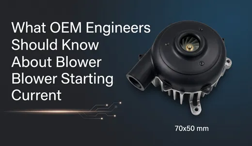
Engineering Warning: The Nameplate Pitfall
A widespread mistake in OEM electrical design is relying solely on steady-state Full Load Amperage (FLA) to select line fuses, wiring harnesses, and protection switches. According to NEMA MG 1-2021 (Section 12.38), standard AC induction motor Locked Rotor Amperage (LRA) can exceed nominal FLA by 500% to 700%. Furthermore, modern electronically commutated (EC) and brushless DC (BLDC) blowers exhibit completely different start-up dynamics that must be analyzed independently.
Statistical field metrics provided in U.S. DOE Motor Systems Tip Sheet #6 reveal that approximately 22% of industrial motor controller field disruptions originate directly from inaccurate starting current estimations rather than physical motor hardware defects. Thoroughly evaluating starting current dynamics is therefore an absolute necessity for robust hardware engineering.
1. Distinguishing Core Electrical Parameters: FLA vs. LRA
To master starting current design, engineers must first establish a clear distinction between two critical parameters found on motor nameplates and technical datasheets:
- Full Load Amperage (FLA): The steady-state root-mean-square (RMS) current drawn by the Air Blower when operating under nominal supply voltage, maximum rated aerodynamic load, and standardized ambient temperature conditions. FLA governs continuous heat dissipation, long-term conductor sizing, and overall thermal budgets.
- Locked Rotor Amperage (LRA): The peak transient current drawn by an AC induction motor at the precise instant voltage is applied while the rotor is stationary. For traditional single-phase and three-phase AC induction blowers. High-torque industrial centrifugal blowers may experience transient spikes up to 800% of FLA.
LRA is a brief transient phenomenon rather than a permanent state. For conventional AC induction blowers, the initial high-current phase typically lasts between 0.1 and 0.5 seconds. However, if the system possesses high mechanical inertia—such as large-diameter aluminum impellers—the acceleration phase expands, sustaining high current draw for 1.0 second or longer. Technical analysis from the Eaton Motor Protection Application Whitepaper (2024) indicates that motor loads requiring acceleration times above 0.7 seconds will routinely cause standard Type B circuit breakers to trip, requiring specialized Type D breakers or time-delay fuses.
In contrast, the high-performance TKFAN Air Blower EC/BLDC series utilizes integrated digital drive architectures with built-in soft-start algorithms. These smart drives clamp starting current to roughly 120% to 200% of nominal FLA, virtually eliminating traditional induction current spikes. This makes EC blowers the preferred choice for medical ventilators, energy storage BMS enclosures, and automotive electronics where maintaining low line noise and minimal bus voltage drop is critical.
2. How Mechanical Load Inertia Dictates Current Duration
Evaluating starting current risk requires measuring both peak magnitude and total duration. The primary variable governing duration is the rotational moment of inertin of the blower impeller:
As codified in AMCA Standard 99-2402 (Fan Dynamics Specification), higher rotational inertia requires higher total acceleration torque, which directly extends the duration of peak current draw. A lightweight, plastic-impeller Air Blower may accelerate to full speed in 0.15 seconds, allowing transient current surges to pass safely below circuit breaker thermal trip thresholds. Conversely, heavy metal impellers designed for high static pressure require 0.8 to 1.5 seconds to achieve operational RPM.
| Blower Motor Technology | Primary Risk Factor | Recommended Protection |
|---|---|---|
| Direct-On-Line AC Induction Blower | Circuit breaker false tripping, contactor arcing | Type D MCB, Time-Delay Fuses, Thermal Relays |
| External Driver BLDC Blower | Incorrect acceleration ramp configuration | Fast-acting DC Fuses, Drive Internal OCP |
| TKFAN Integrated EC Blower | Capacitive DC bus charging surge | Type C MCB, Inrush NTC / Active Soft Start |
System backpressure also impacts start-up performance. If an Air Blower starts against a closed damper or blocked ductwork, the fluid torque load increases substantially, extending acceleration times and maintaining elevated current levels. OEM test engineers should verify blower performance under both open-flow and fully restricted ducting conditions.
3. Comparative Technology Matrix: AC vs. BLDC vs. EC Drive Architectures
Selecting the right motor driver technology determines system electrical behavior. OEM engineering teams generally evaluate three primary blower topologies:
1. Standard AC Induction Air Blower
Direct line-connected AC blowers offer simple, low-cost operation but produce high inrush currents. They are best suited for rugged industrial environments with robust power grids where electrical noise is not a primary concern.
2. External BLDC Controller Blower Systems
External drive BLDC systems allow customizable soft-start acceleration profiles. However, if an OEM sets the ramp time too short during commissioning, the motor will draw high current spikes similar to standard AC units.
3. TKFAN Integrated EC Air Blower Series
TKFAN Air Blower EC models integrate the drive controller directly inside the motor hub. Featuring factory-tuned firmware, soft-start ramps, and over-current protection, these units limit inrush current to under 200% of nominal FLA. Data from the EC Drives Association Market Report (2024) shows that switching from conventional AC blowers to soft-start EC units reduces startup-induced supply voltage dips by over 70%.
4. Electrical Protection Devices Sizing Under NFPA 70 / NEC 430
For systems exported to North America, circuit design must strictly adhere to NFPA 70: National Electrical Code (NEC Article 430).
NEC Article 430.52 dictates that branch-circuit short-circuit and ground-fault protective devices may be sized above nominal FLA to accommodate starting inrush, while maintaining rapid disconnect performance under actual short-circuit fault conditions.
- AC Induction Blower Circuits: Must use Type D MCBs or dual-element time-delay fuses calibrated to handle short-duration LRA surges without tripping. Standard residential Type B breakers should be avoided.
- TKFAN EC Blower Circuits: Because inrush current is digitally clamped, standard Type B or Type C circuit breakers are generally sufficient. Engineers should focus on protecting input stages against line surges and reverse polarity.
- Overload Protection Calibration: Thermal overload relays protect against sustained high current rather than brief starting surges. The relay's trip curve must accommodate motor acceleration time without false tripping during normal startup.
According to the Eaton Motor Protection Application Guide, over 30% of OEM equipment compliance failures during UL 508A and UL 60730 audits result from improper protective device selection for motor starting characteristics.
5. Mitigating Voltage Dips ($\Delta V$) and Bus Disturbances
High transient starting currents draw voltage across supply conductors and power source internal impedances, producing line voltage dips :
As defined in IEC 61000-4-11, if line voltage dips exceed 10% for longer than 20 milliseconds, nearby sensitive electronics—such as PLC controllers, sensors, touchscreen displays, and CAN/RS485 communication chips—may reset or report spurious data errors.
Recommended Engineering Mitigation Measures
- Reduce Conductor Resistance: Increase wire gauge (AWG) and minimize cable length between the power supply and the blower unit.
- Deploy TKFAN Soft-Start EC Blowers: Clamping peak current to minimizes supply voltage drop at the source.
- Separate Power Buses: Route motor power lines separately from sensitive low-voltage digital control electronics.
- Add Bus Capacitance: Install electrolytic buffer capacitors or DC-bus stabilization modules near driver input terminals to absorb transient current surges.
6. Comprehensive System Verification and Waveform Testing Protocols
Calculations alone cannot substitute for empirical testing. OEM design teams should capture actual starting current waveforms during prototype validation using high-sample-rate digital oscilloscopes equipped with precision current probes.
Figure 1: Oscilloscope comparison of starting current dynamics: Standard AC induction inrush vs. TKFAN EC Blower soft-start profile.
Testing should evaluate three critical worst-case operating conditions:
- Maximum Aerodynamic Backpressure: Starting the blower with fully restricted air ducts.
- Minimum Input Voltage Line Bound: Testing at of nominal line voltage, where motors draw higher current to achieve required startup torque.
- Thermal Extremes: Verifying startup performance at maximum rated operating temperature.
7. Step-by-Step OEM Selection Workflow for TKFAN Air Blower Integration
To optimize air blower selection and minimize electrical issues, OEM engineering teams should follow a structured evaluation workflow:
- Define Supply Constraints: Determine maximum allowable voltage drop , peak supply current capacity, and circuit breaker ratings.
- Evaluate System Resistance: Determine operating airflow requirements and duct backpressure characteristics.
- Select Optimal Blower Architecture: For sensitive electronics or compact power supplies, specify an integrated soft-start unit from the TKFAN Air Blower Product Catalog. For high-power industrial equipment with robust grid supply, standard AC models may be selected using appropriate LRA design margins.
- Request Technical Test Data: Obtain oscilloscope starting current profiles, rotor moment of inertia values, and recommended protection component lists directly from TKFAN engineering support.
- Prototype Validation: Conduct full system testing under worst-case voltage, thermal, and backpressure conditions prior to production release.
Technical Questions & Answers (FAQ)
Q1: How does locked rotor amperage (LRA) differ from initial inrush current in an Air Blower?
LRA represents the sustained RMS current drawn by an AC motor when the rotor is completely locked at zero speed under full applied voltage. Inrush current includes both this mechanical locking draw and an even shorter sub-transient magnetic saturation spike (lasting 1-2 AC cycles) when voltage is first connected. In practice, protective devices must be sized to tolerate both phenomena.
Q2: Why do TKFAN Air Blower EC models show dramatically lower starting current than traditional AC blowers?
TKFAN EC blowers use integrated digital microcontrollers to synthesize motor phase voltages. Instead of connecting directly across the AC line, the driver ramps frequency and pulse-width modulation (PWM) dynamically. This controls motor slip, limits peak phase current to roughly 1.2 to 2.0 times FLA, and ensures smooth mechanical acceleration.
Q3: Can an OEM use a standard Type B circuit breaker for an AC-driven Air Blower?
It is generally not recommended. Standard Type B breakers trip instantly at 3 to 5 times nominal rating. Because standard AC induction air blowers draw 5 to 7 times FLA during startup, a Type B breaker will routinely trip on inrush. A Type D or specialized motor circuit protector should be used instead.
Q4: How does high aerodynamic duct backpressure affect blower starting current?
Starting against high backpressure increases resistive torque on the impeller. For AC induction motors, this extends the time required to accelerate to full operating RPM, prolonging the high LRA phase and increasing the risk of thermal overload or circuit breaker tripping.
Q5: What is the main cause of PLC controller resets when an Air Blower starts up?
PLC resets are typically caused by voltage dips on the common DC or AC supply bus. When a high-inrush motor starts, the temporary current spike creates a voltage drop across system wiring resistance. If the bus voltage drops below the PLC's minimum operating threshold for more than 10-20 ms, the controller will restart.
Q6: Do EC Blowers create any starting current issues despite having integrated drivers?
While EC motor windings do not experience high LRA spikes, the driver's internal DC bus capacitors draw a brief capacitive charging current when AC/DC power is first applied. If many EC blowers are switched on simultaneously, this charging current can trip upstream protection devices unless appropriately buffered.
Q7: How does environmental temperature influence Air Blower starting current profiles?
At low temperatures, lubricant viscosity in motor bearings increases, adding mechanical resistance and extending acceleration time. At elevated temperatures, winding resistance increases while component thermal limits drop, making thermal overload switches more sensitive to standard startup surges.
Q8: What electrical standards govern protective device selection for industrial Air Blowers exported to the USA?
The primary governing standard is NFPA 70 (National Electrical Code), specifically Article 430. Component construction, short-circuit ratings, and thermal protection safety are evaluated under UL 508A, UL 60730, and UL 1004 standards.
Q9: How can OEM engineers accurately capture transient inrush current on a prototype machine?
Measurements should be performed using a high-bandwidth digital storage oscilloscope coupled with a calibrated Hall-effect current probe or Pearson current transformer. The system should sample at to capture peak amplitude, sub-transient duration, and total settling time back to steady-state FLA.
Q10: Where can OEM engineers source detailed oscillograms and CAD models for TKFAN Air Blower products?
Full engineering specifications, 3D CAD files, moment of inertia metrics, and test oscillograms are available directly through the official TKFAN Air Blower Product Portal or by contacting TKFAN application support.
GET A QUOTE