

High Pressure Blower Design for Restricted Airflow: Overcoming High Backpressure Thermal Challenges with TKFAN Solutions
Modern industrial equipment, medical devices, automotive electronics, and high-end manufacturing systems are evolving rapidly toward high component density, ultra-compact enclosures, and narrow internal ventilation pathways. Mechanical and thermal engineers frequently face a frustrating engineering roadblock: severely restricted airflow caused by dense PCB stacks, tight internal bends, particulate HEPA filters, micro-channel heat sinks, and tortuous ducting. While conventional axial fans deliver impressive volumetric airflow in open-air conditions, their aerodynamic performance degrades rapidly when confronted with high system impedance. Airflow stalls, heat accumulates in sensitive zones, operational performance drops, and critical machinery suffers unexpected failures.
This critical bottleneck is precisely where a specialized High pressure blower transforms system performance. Unlike standard axial cooling fans, an advanced air blower utilizes radial aerodynamic structures to generate massive static pressure, forcing cooling air through heavily obstructed pathways. The complete lineup of TKFAN High pressure blower units is engineered with optimized mechanical geometry and driven by high-efficiency brushless DC motors. Every P-Q (pressure vs. flow) curve is systematically validated for restricted airflow environments. If you are selecting a reliable thermal management solution for high backpressure applications, explore the full product specifications here: TKFAN High Pressure Blower Catalog.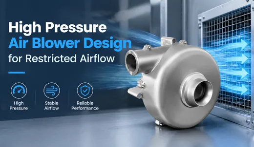
Understanding Restricted Airflow: Why Standard Cooling Devices Fail
Restricted airflow refers to any thermal management operational scenario characterized by substantial system backpressure (pressure drop). System impedance naturally originates from essential internal components, including HEPA filtration media, extended or corrugated flexible hoses, dense micro-channel cold plates, tightly packed electronic boards, narrow chassis channels, and specialized porous media such as medical respiratory masks or fuel cell stacks.
Design engineers often initially select standard axial fans because they provide high CFM (cubic feet per minute) ratings in open-air environments at a lower upfront unit cost. However, the fluid dynamics of an axial fan limit its ability to build significant static pressure. When air encounters physical obstacles inside a sealed enclosure, the required system static pressure spikes, shifting the axial fan into an aerodynamic stall zone. Even if the impeller spins at maximum rated RPM, actual air circulation through the chassis drops dramatically.
Common Failure Symptoms in High Impedance Systems:
- Actual semiconductor junction temperatures exceed CFD thermal simulation estimates.
- Local hot spots develop around power modules, RF components, and optical sensors due to localized air stagnation.
- Fan motors overheat, and ball bearings suffer premature wear while fighting continuous high static impedance.
- Process air output becomes unstable in automated gas sampling, 3D printing exhaust, and clinical medical equipment.
Thermal simulations often underestimate the real-world pressure drops introduced by real-world filters and complex ducting. Even with advanced CFD modeling, relying solely on open-air fan specifications while ignoring the full P-Q performance curve leads to critical design flaws. Utilizing a high-performance TKFAN air blower solves this structural limitation by delivering sustained, effective airflow across high backpressure loads, mitigating the thermal risks associated with underpowered axial fans.
Core Mechanical Principles of High Pressure Blower Engineering
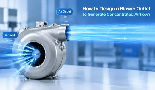
The aerodynamic working principle of a centrifugal air blower differs fundamentally from an axial fan. Air enters the blower axially along the central motor spindle; the rapidly spinning impeller accelerates the air outward in a radial direction using centrifugal force. The air is then compressed inside the specialized volute housing before discharging at a 90-degree angle through the tangential outlet. This mechanical arrangement efficiently converts motor rotational energy into high static pressure rather than unconfined volume flow.
1. Aerodynamically Tuned Impellers
Impeller geometry dictates pressure building capabilities. A TKFAN High pressure blower utilizes precision curved blades optimized for static pressure accumulation under heavy impedance. High-strength composite impellers spin up to 55,000 RPM without structural deformation. Every single impeller undergoes automated dual-plane dynamic balancing to eliminate vibration and preserve bearing longevity.
2. Pressure-Optimized Volute Housings
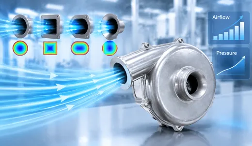
The volute housing surrounding the impeller converts dynamic velocity into usable static pressure through a gradually expanding cross-sectional area. TKFAN independently customizes volute profiles for every blower size—from compact 50mm micro blowers to 209mm heavy industrial units—ensuring maximum pressure recovery through narrow ducts.
3. High-Speed 3-Phase BLDC Drives
Continuous backpressure demands exceptional torque and speed. Driven by custom 3-phase brushless DC motors (available in 12V DC, 24V DC, and 220V AC), every TKFAN air blower offers integrated or external driver boards. Standard 4-wire control options include PWM speed regulation and FG tachometer feedback for intelligent closed-loop control.
4. Rugged Industrial Reliability
Operating continuously against restricted airflow imparts high mechanical stress. TKFAN blowers feature dual precision ball bearings rated for over 50,000 hours of continuous operation. Optional IP55, IP67, and IP68 vacuum epoxy potting protects windings against moisture, dust, and chemical exposure, while UL 94 V-0 flame-retardant plastics ensure global compliance.
TKFAN High Pressure Blower vs. Standard Air Blower Performance
Not all blowers perform reliably when backpressure escalates. Low-cost standard blowers may display attractive open-air CFM figures, but their P-Q curves drop sharply at moderate resistance levels. A genuine High pressure blower must maintain flat, sustained airflow even as system resistance rises.
Below is a performance comparison of representative TKFAN air blower models designed for high-impedance operations:
| Model Number | Dimensions (mm) | Voltage | Max Static Pressure | Max Airflow | Speed (RPM) |
|---|---|---|---|---|---|
| BA5025H24B-A | 50 × 50 × 25 | 24V DC | 4.81 kPa | 11.1 CFM | 38,000 |
| BA5030H12B-A | 58 × 50 × 28 | 12V DC | 6.15 kPa | 8.6 CFM | 39,100 |
| BA7050H24B-C | 72 × 60 × 42 | 24V DC | 9.14 kPa | 16.0 CFM | 40,000 |
| BA8060H24B-E-25kpa | 80 × 80 × 60 | 24V DC | 24.00 kPa | 28.0 CFM | 55,000 |
When reviewing thermal specifications, remember that open-air CFM represents zero resistance. In real-world restricted airflow applications, maximum static pressure and the complete P-Q curve serve as the true engineering benchmarks. Complete performance curves and datasheet downloads are accessible at https://www.tkfan.com/products/airblower/high-pressure-blower.html.
Key Industry Applications for TKFAN High Pressure Blower Systems
Restricted airflow challenges span multiple advanced technology sectors. The following operational examples demonstrate how selecting the correct TKFAN High pressure blower delivers critical thermal and pneumatic performance in demanding real-world environments.
Medical Respiratory & Therapy Equipment
Continuous Positive Airway Pressure (CPAP) devices, APAP units, High-Flow Nasal Cannula (HFNC) machines, and portable ventilators present severe airflow restrictions. Air must traverse internal bacterial filters, narrow patient tubing, humidifier chambers, and breathing masks, creating variable system backpressure. A compact TKFAN High pressure blower (such as the BA5025 or BA7050 series) provides rapid pressure response times, smooth pressure maintenance, and whisper-quiet acoustic signatures critical for bedside patient comfort.
Hydrogen Fuel Cell Power Systems
Hydrogen fuel cell stacks require precise, continuous oxygen delivery directly across dense gas diffusion layers (GDL). This structural setup creates intense backpressure inside the supply manifold. A high-efficiency air blower overcomes GDL flow resistance to deliver metered reaction air. Utilizing a closed-loop TKFAN air blower with PWM control allows system designers to dynamically scale airflow in real time as electrical demand fluctuates, protecting fuel cells from power starvation.
3D Printing & Industrial Laser Processing
Industrial additive manufacturing systems rely on targeted high-pressure air streams directed through narrow nozzles to cool extruded polymers instantly. Concurrently, laser cutting and engraving machinery require robust extraction units to clear heavy smoke, corrosive fumes, and particulate matter through particulate filters and long exhaust hoses. Standard cooling fans fail under these high static pressures, whereas a heavy-duty High pressure blower preserves strong extraction velocities, protecting optical lenses and ensuring crisp manufacturing tolerances.
Automated Gas Sampling & Environmental Monitoring
Automated air sampling instruments, VOC detectors, and industrial gas analyzers rely on continuous suction to draw ambient samples through fine inline filters, particulate traps, and narrow capillary tubing. Relying on underpowered fans leads to flow drift, inaccurate volumetric measurements, and compromised sensor calibration. Deploying a precision TKFAN air blower guarantees stable sample collection rates across changing filter loading conditions.
Autonomous Vehicle Sensor Cleaning Systems
Self-driving vehicles require clear visual paths for LiDAR units, cameras, and radar modules. Rain, mud, dust, and road grime blind optical sensors rapidly. Compact, ultra-high-speed TKFAN High pressure blower units generate powerful, targeted air blasts through tiny distribution nozzles, blowing away surface debris instantly without requiring bulky compressor tanks or maintenance-heavy pneumatic systems.
Step-by-Step Selection Guide for High Pressure Blower Integration
Selecting the optimal air blower for restricted airflow environments requires a systematic methodology beyond matching physical dimensions or open-air CFM. Follow this engineering procedure when specifying a TKFAN High pressure blower:
- Calculate Total System Pressure Drop (Impedance): Aggregate all pressure losses across filters, duct bends, internal chassis restrictions, and heat sinks at your target operating flow rate. Physical prototype testing provides the most accurate baseline measurements.
- Evaluate the Full P-Q Curve: Cross-reference your calculated operating point (Required Flow at Required Static Pressure) against full blower curves. Ensure the blower provides a 20% to 30% static pressure safety margin to account for filter dust accumulation over time. Download complete P-Q charts at TKFAN High Pressure Blower Portal.
- Verify Physical Envelope & Mounting Constraints: Match physical footprint, outlet port dimensions, and orientation requirements. TKFAN offers sizes ranging from 50mm micro blowers to 209mm industrial models to fit tight spatial constraints.
- Match Electrical & Control Architecture: Verify input voltage requirements (12V DC, 24V DC, or 220V AC), driver location (integrated internal vs. rugged external driver), and control interface needs (4-wire PWM input with FG speed signal feedback).
- Specify Environmental & Regulatory Protections: Identify required ingress protection ratings (IP55, IP67, IP68 potting), operating temperature limits (-20°C to +70°C standard), UL 94 V-0 flame resistance, and global certifications (CE, RoHS, REACH).
- Request Samples & Perform Validation Testing: Prototype testing inside actual enclosures validates thermal models under real-world backpressure conditions. TKFAN provides rapid sample turnaround times within 3 to 5 business days, with full OEM/ODM mass production delivered in 3 to 4 weeks.
Common System Design Mistakes to Avoid
Even when integrating a premium TKFAN High pressure blower, system-level design mistakes can impair overall thermal efficiency. Avoid these common engineering traps:
- Relying Exclusively on Open-Air CFM Specifications: Free-air CFM values reflect zero backpressure. Always evaluate performance at your system's specific operating point along the P-Q curve.
- Ignoring Intake Path Restrictions: Restricting the inlet side of a blower creates unwanted vacuum pressure, dropping performance as severely as an obstructed discharge port. Ensure adequate inlet clearance.
- Underestimating Filter Loading Impedance: Clean HEPA filters present far less resistance than dirty ones. Designing without a 20-30% pressure reserve leads to thermal failures as equipment collects dust in the field.
- Neglecting Structural Vibration Isolation: High-speed impellers spinning up to 55,000 RPM generate micro-vibrations. Use flexible coupling boots and isolation grommets to prevent acoustic amplification across sheet metal chassis.
Technical Questions & Answers (FAQ)
What is the primary difference between a high pressure blower and a standard axial fan in restricted airflow conditions?
Standard axial fans deliver high open-air airflow but collapse under static pressure. A high pressure blower uses centrifugal force to convert kinetic motor energy into high static pressure, driving air through dense filters, narrow ducts, and high-impedance enclosures where axial fans stall.
What maximum static pressure output can TKFAN High pressure blower models achieve?
The TKFAN High pressure blower product series covers static pressures ranging from 1.98 kPa up to 24.00 kPa (such as the BA8060 flagship model operating at 55,000 RPM), accommodating moderate resistance to extreme industrial backpressure.
Do TKFAN air blower models support PWM speed control and tachometer feedback?
Yes. Most TKFAN air blower units feature a standard 4-wire interface supporting PWM speed modulation and FG tachometer signal output, allowing host controllers to adjust blower speeds dynamically based on real-time thermal or pressure demand.
Are TKFAN high pressure blowers suitable for medical CPAP and ventilator applications?
Yes. Compact models like the BA5025 and BA7050 series are specifically optimized for medical devices, delivering rapid pressure response times, low acoustic vibration, and reliable continuous airflow through patient delivery circuits.
What IP ingress protection options are available for harsh environmental operating conditions?
TKFAN offers customized IP55, IP67, and IP68 protection using vacuum epoxy potting and conformal coatings to safeguard internal BLDC driver circuits and motor windings against moisture, fine dust, and corrosive vapors.
What is the standard operating temperature range for a TKFAN High pressure blower?
Standard industrial-grade TKFAN High pressure blower units operate reliably across an ambient temperature range of -20°C to +70°C (-4°F to +158°F). Extended temperature configurations are available upon request.
Can TKFAN customize air blower hardware for specialized OEM/ODM project requirements?
Yes, TKFAN provides comprehensive OEM/ODM customization, including tailored wiring harnesses, modified mounting flanges, custom PWM response curves, unique discharge nozzle geometries, and specialized operating voltages.
Why is dynamic balancing critical for high-speed centrifugal blowers?
At rotational speeds up to 55,000 RPM, minor weight imbalances generate intense centrifugal vibration, causing high acoustic noise and premature ball bearing failure. TKFAN performs 100% automated dual-plane dynamic balancing on every impeller during manufacturing.
How does a closed-loop TKFAN air blower improve fuel cell system performance?
By delivering metered, high-pressure reaction air directly across dense gas diffusion layers, a closed-loop TKFAN air blower prevents oxygen starvation during peak load transitions, maximizing stack output and energy conversion efficiency.
What is the typical turnaround time for engineering samples and mass production orders?
Standard product samples ship within 3 to 5 business days for rapid prototype evaluation. Custom OEM/ODM production orders typically feature a production lead time of 3 to 4 weeks.
Managing restricted airflow and overcoming high backpressure impedance are essential requirements in modern medical, automotive, energy, and industrial electronics design. When conventional axial fans fail under static load, engineered high-pressure centrifugal blowers provide the continuous pressure and airflow required to keep systems operational. Driven by aerodynamically tuned impellers, high-speed 3-phase brushless motors, and durable mechanical housings, the full lineup of TKFAN High pressure blower solutions provides reliable thermal and pneumatic performance for high-impedance applications. Explore complete datasheets, download engineering P-Q curves, or request customized OEM support directly at https://www.tkfan.com/products/airblower/high-pressure-blower.html.
GET A QUOTE