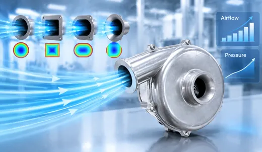


Air Blower Noise Reduction Strategies for High-Speed Applications
High-speed, compact fluid power components represent the thermal and pneumatic backbone of cutting-edge technological systems. Modern engineering applications rely heavily on specialized centrifugal machinery to provide intense pressure heads across restrictive environments. From non-invasive medical ventilators and hydrogen fuel cell anode recirculation systems to autonomous vehicle LiDAR optical cleaning modules and industrial additive manufacturing exhaust systems, the demand for a reliable High pressure blower has surged exponentially. Equipment designers depend on these miniature powerhouses to generate continuous static pressure, overcoming dense downstream filtration resistance, narrow manifold passages, and steep fluid circuit backpressures.
However, running small impellers at extreme operational velocities introduces a severe engineering hurdle: intense, unmitigated air blower noise. As rotational velocities escalate from 30,000 RPM to 45,000 RPM—and reach upwards of 55,000 RPM in ultra-compact performance units—the acoustic signature changes dramatically. Complex aerodynamic turbulence, high-frequency structural vibration, electromagnetic torque pulsations, and volumetric chamber resonance coalesce into an intrusive noise profile. Excessive air blower noise not only ruins end-user experience and violates occupational health regulations, but it also signals underlying mechanical stress, energy loss, and potential premature hardware degradation.
Design teams often find themselves trapped in a classic performance compromise. They must maximize static pressure delivery and volumetric airflow output using a high-efficiency TKFAN air blower while keeping acoustic emissions down to ultra-quiet levels. Crucially, noise reduction must be achieved without expanding equipment physical footprints, compromising cooling air passages, or driving up total bill-of-materials (BOM) costs. Too often, noise mitigation is treated as an afterthought—an late-stage patch consisting of heavy external silencers or dense sound-absorbing foam. Unfortunately, retrofitted acoustic baffles frequently choke fluid pathways, create massive parasitic pressure drops, and negate the precise advantages that made a High pressure blower necessary in the first place.
This technical guide systematically dissects the root causes of acoustic radiation in high-speed centrifugal systems. By analyzing primary noise sources alongside system-level acoustics, product development teams can evaluate actionable mitigation pathways. Featuring empirical data and verified design practices from the official TKFAN High pressure blower catalog, this guide equips OEM engineers with practical methods to achieve maximum static performance alongside refined sound signatures.
Deconstructing Acoustic Sources in High-Speed Air Blowers
Effective acoustic engineering requires breaking down total acoustic pressure output into discrete physical mechanisms. In high-speed operating environments, total air blower noise stems from four distinct physical domains: aerodynamic sound, mechanical vibration, motor electromagnetic pulsation, and system-level acoustic resonance. Advanced micro-blowers—such as the TKFAN BA8060H24B-E (48,000 RPM max speed, 18 kPa max pressure) and the BA8060H24B-E-25kpa (55,000 RPM max speed, 24 kPa max pressure)—display distinct modal behaviors across these acoustic paths.
| Noise Category | Physical Mechanism | Dominant Frequency Character | Primary Mitigation Focus |
|---|---|---|---|
| Aerodynamic | Blade passing pulses & turbulence shear | High-frequency discrete tones & broadband noise | CFD impeller design & tongue spacing |
| Mechanical | Mass imbalance & bearing surface friction | Rotational frequency harmonics (1X RPM) | Dynamic balancing (G2.5) & ball bearings |
| Electromagnetic | Phase commutation & PWM switching | Harmonic motor hum & carrier frequency whistle | Sine-wave FOC drive & >20kHz PWM |
| Structural Resonance | Chassis coupling & cavity wave amplification | Broadband amplification & standing waves | Isolators, dampening pads & smooth ducting |
1. Aerodynamic Sound Generation (The Primary Driver)
Aerodynamic sources account for 60% to 80% of total acoustic power in high-speed miniature blowers. Aerodynamic acoustic radiation splits into two distinct operational phenomena: discrete tonal sound generated by Blade Pass Frequency (BPF) and broadband noise driven by stochastic air turbulence.
As the impeller spins at tens of thousands of RPM, each blade periodically chops through stationary fluid volumes inside the housing. These localized, high-velocity pressure pulses generate sharp acoustic spikes at the Blade Pass Frequency and its higher harmonics. The housing volute tongue—the narrow junction separating the fluid exit scroll from the outer impeller diameter—is the focal point for BPF sound generation. When the radial clearance between blade tips and the volute tongue is too small, localized pressure spikes intensify, producing a sharp, high-pitched whistle that human ears readily detect.
Conversely, broadband aerodynamic sound stems from boundary layer separation on blade surfaces, vortex shedding off trailing edges, blade-tip leakage currents, and chaotic turbulent mixing inside the volute chamber. Acoustic power generated by turbulence scales with blade-tip velocity to the 5th or 6th power. Consequently, even small increases in motor rotational speed produce massive spikes in total air blower noise. This phenomenon highlights why ultra-compact blowers must utilize refined aerodynamic geometry rather than relying solely on raw motor RPM to deliver high pressure heads. Distorted inlet conditions, intake blockages, or abrupt 90-degree duct bends immediately upstream magnify vortex formation, elevating broadband acoustic output across all spectrums.
2. Mechanical Vibration and Structural Radiation
Even with optimal fluid dynamic design, physical manufacturing variances introduce mechanical forces. Mechanical vibration creates direct sound radiation and transmits dynamic energy into adjacent equipment structures, causing them to radiate sound like a speaker cone. Primary mechanical drivers include rotational mass imbalance, bearing track friction, shaft deflection, and hardware looseness.
At rotational speeds exceeding 30,000 RPM, even microgram-level mass offsets generate massive centrifugal forces . Without precision dynamic balancing, these rotational forces travel into mounting points and flex surrounding enclosure panels. Dual ball bearings are essential for sustained long-term operation; however, lower-grade or worn bearing assemblies generate surface friction noise, elevating background noise floor levels and shortening service life. Every TKFAN High pressure blower impeller undergoes automated two-plane dynamic balancing according to ISO 1940 G2.5 standards. This rigorous NVH control keeps structural vibration to absolute minimums across 50,000+ hours of continuous duty.
3. Motor Electromagnetic Pulsations
Modern compact high-pressure units rely on Brushless DC (BLDC) motors for driving torque. However, BLDC phase commutation inherently produces electromagnetic torque ripple, heard as a distinct motor hum. Traditional trapezoidal commutation creates sharp torque transitions, yielding noticeable electrical hum under heavy fluid loading. In contrast, sinusoidal Vector Control / Field Oriented Control (FOC) smooths current transitions, reducing electrical torque spikes. Additionally, if the inverter Pulse-Width Modulation (PWM) switching frequency resides inside the audible band (below 18 kHz), it introduces an intrusive high-frequency whistle into overall TKFAN air blower noise. Advanced drive architectures inside select TKFAN units integrate high-frequency sinusoidal FOC driving to eliminate electrical acoustic signatures.
4. System-Level Structural Acoustic Coupling
A common hurdle for OEM integration engineers is structural noise amplification: a TKFAN air blower that operates quietly on a lab bench may sound significantly louder once installed inside a rigid equipment cabinet. This amplification occurs when rotational excitation frequencies coincide with the natural structural resonances of surrounding sheet metal, mounting plates, or internal fluid conduits. When excitation aligns with structural resonant modes, mechanical energy converts into severe cabinet vibration, radiating amplified sound pressure into the surrounding environment.
Source-Level Mitigation: Optimizing the Blower Hardware
The most cost-effective path to acoustic performance is addressing noise directly at the component level during unit selection, rather than relying on heavy aftermarket acoustic enclosures. Engineers looking to integrate high-efficiency hardware can explore the baseline acoustic profiles of the TKFAN air blower family to leverage built-in NVH engineering features.
Aerodynamic Impeller and Volute Refinement
- Backward-Curved Airfoil Blades: Compared to basic straight or forward-curved blades, backward-curved airfoil geometry reduces boundary layer separation and suppresses trailing-edge vortex shedding. This configuration achieves high static pressure efficiency while lowering broadband acoustic output. CFD-driven blade geometry sits at the heart of the entire TKFAN High pressure blower line.
- Serrated / Slotted Impeller Trailing Edges: Incorporating bionic serrations along blade trailing edges breaks large coherent turbulent vortices into smaller structures. This distributes acoustic energy across a broader frequency spectrum, smoothing out tonal acoustic spikes. This modification preserves volumetric airflow while lowering peak acoustic levels in compact units like the BA5025H24B-A (50x25mm).
- Modified Volute Tongue Geometries: Increasing radial clearance and employing inclined or stepped volute cut-off angles disrupts synchronized pressure pulses produced as blades pass the tongue. Slanted volute geometries spread blade-pass energy over time, reducing peak tonal BPF noise.
- Smooth Inlet Bellmouth Contours: Bellmouth-shaped inlet transitions eliminate sharp corners at the air intake, preventing flow separation and turbulence right at the entering edge. Smooth inlet velocity profiles lower the baseline acoustic floor during high-velocity operation.
Mechanical Precision and High-Damping Housings
Achieving whisper-quiet performance requires combining aerodynamic refinements with strict mechanical tolerances. Implementing precision dual ball bearings alongside automated dynamic balancing reduces rotational vibration forces. This minimizes vibration transmission into host equipment and prevents structural resonance coupling. Furthermore, motor drive selection should prioritize sinusoidal FOC drive topology over basic trapezoidal switching, while setting PWM carrier frequencies above 20 kHz to push switching noise outside human hearing thresholds.
Material selection plays an equally vital role in acoustic attenuation. Polymeric blower housings act as acoustic barriers. Engineering plastics formulated with high internal damping coefficients absorb internal vibration better than thin, unreinforced rigid shells. Every TKFAN air blower housing uses RoHS-compliant, UL 94 V-0 flame-retardant polymers that balance fire safety, mechanical rigidity, and internal acoustic absorption.
Intelligent Speed Management (PWM Closed-Loop Control)
All high-speed TKFAN High pressure blower models feature standard 4-wire PWM control inputs and tachometer FG signal outputs. Intelligent closed-loop speed control provides a direct way to minimize operational noise across real-world duty cycles:
- Speed-to-Demand Tuning: Program control loops to run the unit at the lowest RPM necessary to satisfy real-time pressure and flow requirements. Avoid running at 100% full speed continuously, as small RPM reductions yield substantial decreases in acoustic output due to tip-speed velocity scaling laws.
- Dynamic Thermal & Pressure Adaptation: Implement dynamic control logic that dials back RPM during low-load operating states. Applications like medical ventilators, fuel cell purge routines, and equipment cooling systems operate at partial capacity most of the time, where reduced fan speeds dramatically improve acoustic comfort.
- Avoid Aerodynamic Stall Zones: Keep minimum operating speeds safely above the stall region on the P-Q performance curve. Operating a centrifugal unit within its stall margin creates severe flow separation, leading to erratic pressure fluctuations, high acoustic turbulence, and motor stress. Engineers should consult official P-Q performance curves from the TKFAN air blower catalog during system specification.
System-Level Integration: Acoustic Best Practices for OEMs
Even an intrinsically quiet component can produce high noise levels if surrounding mechanical mounting, ducting layouts, and cabinet interiors are poorly designed. Integrating a high-speed TKFAN High pressure blower requires applying solid system-level NVH mitigation techniques.
System Engineering Tip: Never attach a high-speed blower housing directly to thin sheet metal panels or un-damped structural ribs. Structural isolation prevents solid-body vibration transmission and avoids turning host equipment cabinets into acoustic sounding boards.
Vibration Isolation and Structural Decoupling
- Elastomeric Isolation Mounts: Place tailored silicone, shore-A rubber, or fluoroelastomer dampening grommets between the blower housing and rigid chassis mounts. Ensure isolator durometer ratings are tuned so the natural isolation frequency sits well below the lowest motor operating speed.
- Flexible Duct Connections: Avoid connecting rigid plastic or aluminum piping directly to blower intake or discharge ports. Rigid connections act as acoustic bridges, carrying mechanical vibrations down the entire ductwork path. Use flexible silicone, rubber, or reinforced textile sleeves to interrupt vibration transmission.
- Fastener Torque Standardisation: Over-tightening mounting screws crushes rubber grommets, bypassing their elastic isolation properties and creating rigid contact points. Always adhere to specified assembly torque limits provided in technical documentation.
Acoustic Ductwork and Flow Pathway Design
Duct layout downstream and upstream of the unit heavily influences overall acoustic performance. Abrupt directional changes or poor cross-sectional transitions create secondary turbulence, elevating total system acoustic energy:
- Maintain straight duct runs equal to at least 2 to 3 times the pipe diameter immediately upstream of the intake and downstream of the exhaust. Avoid placing sharp 90-degree elbows right at connection ports; if turns are mandatory, use large-radius elbows fitted with internal turning vanes to maintain smooth flow profiles.
- Design smooth, gradual expansion and contraction transitions (taper angles under 15 degrees) along internal ductwork to prevent flow separation and pressure spikes caused by sudden cross-sectional changes.
- When stringent noise thresholds must be met, install compact inline absorption silencers aligned with system pressure budgets. Silencers must be sized carefully to prevent high pressure drops that would force the TKFAN High pressure blower to run at elevated RPMs, offsetting acoustic gains.
Cabinet Acoustic Treatment and Enclosures
When installing high-speed units inside sealed host equipment chassis, apply targeted cabinet acoustic treatments:
- Apply constrained-layer damping (CLD) sheets to large, unsupported cabinet metal or plastic panels to dampen panel resonance and prevent structural sound radiation.
- Line internal housing walls with open-cell polyurethane or hydrophobic acoustic foam to absorb airborne acoustic energy inside the chamber. Ensure foam materials do not restrict or block air intake paths.
- Ensure internal cavity resonant frequencies do not align with discrete motor BPF tones. Acoustic simulation tools can model enclosure cavity modes during the initial design phase.
Real-World Field Applications & Case Analysis
Noise thresholds vary significantly across industries, requiring customized design trade-offs during system development.
Medical Respiratory Care (CPAP / BiPAP / High-Flow Oxygen)
Home-care medical devices demand extremely quiet operation to avoid disturbing patient sleep cycles. Compact units like the TKFAN BA5025H24B-A and BA7050 series are widely deployed in these medical systems.
- Selection Focus: Choose customized low-noise units equipped with sinusoidal motor commutation, precision dynamic balancing, and noise-optimized impellers.
- System Implementation: Fully decouple the blower assembly using multi-point elastomeric suspensions to isolate structural vibrations from outer plastic housings.
- Flow Path Tuning: Maintain generous spacing between HEPA air intake filters and blower inlet ports to prevent velocity profile distortions that trigger broadband acoustic spikes.
Hydrogen Fuel Cell Cathode Air Delivery
Fuel cell stacks demand precise, high-pressure air delivery to overcome resistance across dense gas diffusion layers (GDL). High-speed units deliver the static pressures needed to maintain chemical reaction rates under varying electrical loads. System isolation and flexible ducting are crucial in these configurations, while inline silencers must be carefully matched to prevent parasitic pressure losses from degrading total system fuel efficiency.
Autonomous LiDAR & Camera Optical Cleaning Systems
Automotive sensor cleaning modules utilize compact high-speed blowers to blast compressed air jets across optical lenses, clearing water droplets, mud, and road debris. These systems must operate reliably across wide temperature ranges (-40°C to +85°C) while enduring continuous vehicle chassis vibration. Integrating a ruggedized, IP68-rated TKFAN High pressure blower with compliant rubber mounts isolates high-frequency operational vibration, keeping cabin interior sound levels low.
Industrial Additive Manufacturing & Laser Fume Extraction
3D printing systems and laser cutters rely on high-pressure fluid circuits to remove dense particulates and recirculate inert cover gases. While industrial noise allowances are broader than medical standards, unmitigated acoustic emissions degrade operator environments. Design strategies focus on optimizing duct routing, installing exhaust mufflers, and utilizing speed control to run units below maximum RPM during light processing cycles.
Frequently Asked Questions: TKFAN Air Blower Noise & Performance
Conclusion
Managing acoustic levels in high-speed centrifugal systems requires balancing aerodynamic performance, mechanical design, electrical motor control, and system isolation. Rather than relying solely on late-stage acoustic retrofits, design teams achieve the best results by addressing noise systematically from component selection through final chassis installation.
Selecting optimized components provides a solid foundation for quiet system performance. For full specification sheets, 3D CAD models, and detailed P-Q pressure performance curves, visit the TKFAN High pressure blower product page. Combining optimized blower hardware with sound system-level integration enables OEMs to deliver robust pressure performance while keeping operational noise well within target limits.