

Brushless Air Blower Motor Control and Efficiency Basics: Complete Engineering Guide
A modern brushless air blower represents an essential class of high-efficiency, electronically commutated centrifugal airflow equipment. Driven by advanced Brushless Direct Current (BLDC) or Permanent Magnet Synchronous Motors (PMSM), these blowers deliver high static pressure, precise airflow regulation, and exceptional continuous-duty reliability across medical, industrial, automotive, and high-tier consumer electronics applications.
Traditional brushed blowers rely on physical carbon brushes for mechanical commutation, creating continuous friction, electrical sparking, carbon dust contamination, and severe mechanical wear. In contrast, premium TKFAN air blower designs eliminate all mechanical sliding contacts inside the motor core. By transferring commutation duties to an intelligent electronic drive controller, a high-performance TKFAN brushless air blower achieves precise dynamic speed regulation, whisper-quiet operation, minimal thermal dissipation, and an operational lifespan spanning tens of thousands of continuous maintenance-free hours.
System integrators, hardware engineers, and OEM product architects frequently encounter critical technical challenges: How do you design a highly stable electronic drive architecture for a high-speed brushless air blower? Which speed control strategy maximizes real-world system efficiency under steep backpressure? How do drive parameters impact overall performance metrics including CFM airflow, static pressure head, transient acceleration, bearing thermal stress, and acoustic noise?
This technical guide explores the foundational operating principles of the TKFAN brushless air blower, compares industry-standard motor control strategies, breaks down the four main sources of energy loss, analyzes closed-loop PID firmware execution, and spotlights a benchmark medical-grade unit: the BA6560H24B-B medical ventilator blower engineered specifically for ICU ventilators and CPAP therapy systems.
What is a Brushless Air Blower? Core Component Breakdown
To optimize drive algorithms and system-level energy efficiency, hardware designers must first evaluate the functional building blocks comprising a modern air blower. Every sub-assembly directly dictates thermal characteristics, dynamic torque capability, and overall fluid power output.
- 3-Phase BLDC Motor Assembly: The electromechanical heart of the TKFAN air blower. It features a permanent magnet rotor (typically high-coercivity Neodymium Iron Boron, NdFeB) paired with a precision-laminated three-phase stator. Commutation is performed electronically via sequential inverter switching rather than carbon brushes. Premium dual precision ball bearings minimize mechanical parasitic drag, enduring continuous extreme RPM conditions.
- Embedded Electronic Drive & Control Board: The neural center of the brushless air blower. This PCB integrates a Microcontroller Unit (MCU) or dedicated gate driver IC, power MOSFET H-bridge inverters, rotor position sensing circuitry (Hall sensors or sensorless back-EMF samplers), voltage regulators, and signal conditioning interfaces. It executes real-time commutation, decodes incoming speed command inputs (PWM or analog VDC), runs closed-loop control algorithms, and provides safety diagnostics.
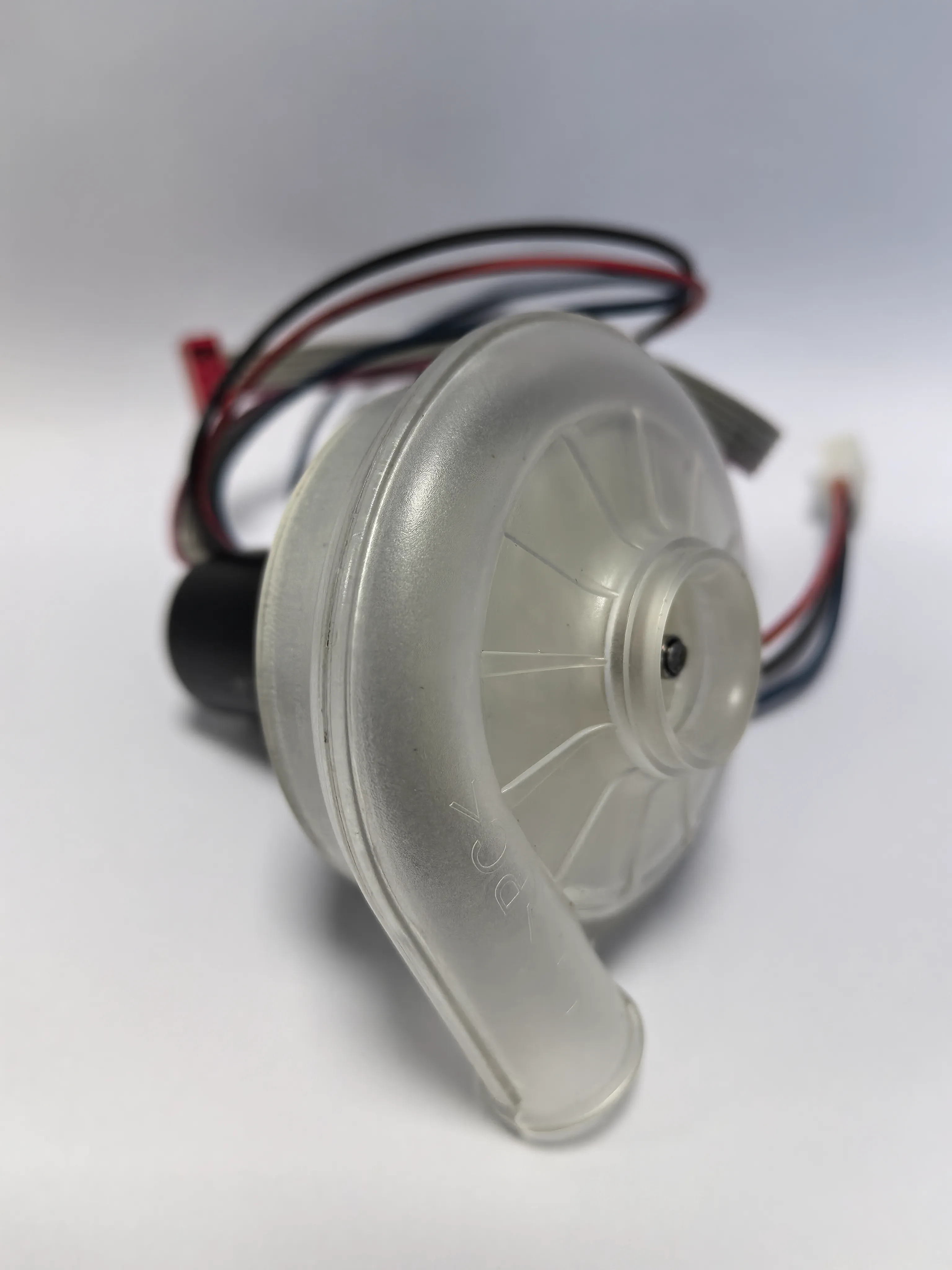
- Aerodynamic Impeller & Volute Housing: The fluid dynamics module. The high-speed rotating impeller imparts kinetic energy to the incoming axial air stream, while the scroll-shaped volute housing converts dynamic velocity pressure into high static pressure through controlled fluid deceleration. Computational Fluid Dynamics (CFD) optimization ensures smooth air acceleration without turbulent boundary layer separation.
- Integrated Wiring Harness & Control Interface: High-grade wiring interfaces supplying DC power lines alongside dedicated low-voltage control input lines (PWM/Analog) and real-time diagnostic output lines (FG tachometer pulses and RD rotor fault alarms).
Brushless Air Blower Motor Control Fundamentals
Unlike brushed DC motors that scale speed linearly by simply varying the applied supply voltage, a brushless air blower cannot function on un-commutated DC power. Electronic driver circuits must continuously synchronize stator coil energization with the exact physical angular position of the rotating permanent magnet rotor while regulating power throughput to hit target speed commands.
Rotor Position Sensing: Hall-Sensor vs. Sensorless BLDC Control
Accurate rotor position feedback is mandatory for switching power MOSFETs at the optimal electrical commutation angle. Two primary methods are utilized in modern TKFAN brushless air blower systems:
- Hall-Effect Sensor Control: Three digital Hall sensors are positioned inside the motor stator at 60° or 120° electrical intervals. These sensors read rotor magnetic pole transitions and feed discrete digital logic states back to the gate controller.
Advantages: Delivers 100% reliable zero-speed startup torque even under heavy static backpressure loads; provides superior low-RPM velocity stability; features straightforward firmware execution. This strategy is standard across critical medical TKFAN air blower designs (such as the BA6560H24B-B) where rapid, smooth, and failsafe acceleration under varying airway resistance is mandatory for patient safety.
Disadvantages: Requires additional internal sensor components, wiring leads, and manufacturing assembly steps. - Sensorless (Back-EMF) Control: Eliminates physical internal magnetic sensors entirely. The driver MCU measures the Back-Electromotive Force (Back-EMF) voltage induced across the un-energized (floating) phase winding during 6-step trapezoidal switching to mathematically determine rotor position.
Advantages: Reduces total Bill of Materials (BOM) cost, simplifies motor internal wiring, and creates an ultra-compact mechanical footprint.
Disadvantages: Requires complex startup alignment sequences; exhibits potential startup stumbles under steep initial static backpressure; susceptible to velocity tracking errors during extreme load transients.
Speed Regulation Strategies: PWM vs. Analog Control
System designers typically select between two standardized control interfaces to modulate speed in a modern brushless air blower:
1. Analog Voltage Speed Control
The system host outputs a continuous DC reference voltage (typically 0–5V or 0–10V) to the driver board. Internal operational amplifiers or ADC pins scale this voltage directly to set motor target RPM. While simple to implement in legacy systems, lowering analog voltage limits the maximum current available during switching, causing motor torque to degrade rapidly at lower operating speeds.
2. Pulse Width Modulation (PWM) Speed Control
The host controller inputs a constant-frequency digital square wave where the active high duty cycle percentage determines target motor RPM (e.g., 10% duty cycle = minimum idle speed, 90% duty cycle = maximum speed). High-performance models like the TKFAN BA6560H24B-B air blower are optimized for PWM input, enabling medical mainboards to seamlessly synchronize blower airflow output with human respiratory cycles in real time.
Core Advantages of PWM Speed Regulation in a TKFAN Brushless Air Blower:
- High Low-Speed Torque Retention: Because power MOSFETs remain driven at full rail voltage during the "ON" phase of the PWM pulse, full magnetic flux is generated, preserving peak motor torque even at low target RPMs.
- Superior Electrical Efficiency: High-frequency solid-state switching minimizes linear voltage drop losses, preventing excessive power dissipation as thermal waste on the driver board.
- Rapid Dynamic Acceleration: Enables sub-second acceleration curves required for advanced medical ventilation modes (such as BiPAP and PSV).
- Seamless Digital Loop Integration: Directly accepts logic outputs from host microcontrollers without requiring expensive Digital-to-Analog Converters (DACs).
Closed-Loop PID Control Architecture
In demanding applications, open-loop speed control is insufficient because external variables—such as supply voltage drift, ambient temperature shifts, and filter dust buildup—cause actual blower RPM to drift away from target setpoints. Premium TKFAN air blower units integrate a full Closed-Loop Proportional-Integral-Derivative (PID) algorithm.
The 5-step closed-loop execution cycle operates continuously in firmware:
- Target Setpoint Acquisition: The MCU reads the incoming command setpoint via PWM duty cycle or analog input.
- Tachometer Feedback Sampling: The driver samples the Frequency Generator (FG) output line, which toggles digital pulses proportional to actual rotor angular velocity.
- Error Value Calculation: The firmware computes real-time error: $\text{Error } e(t) = \text{Target RPM} - \text{Actual RPM}$.
- PID Algorithm Processing:
- Proportional Term (P): Generates an immediate drive correction proportional to the magnitude of current speed error.
- Integral Term (I): Accumulates historical error over time to eliminate steady-state offset under heavy static pressure loading.
- Derivative Term (D): Rates the speed of error change to damp transient overshoot and prevent system oscillation.
- MOSFET Output Adjustment: The PID controller updates duty cycle switching parameters across the inverter bridge, pulling actual blower rotation directly onto the target velocity line.
Hardware Safety & Diagnostic Feedback Signals
High-reliability industrial and medical brushless air blower models feature dedicated hardware lines to communicate system status directly to main device controllers:
- FG Signal (Frequency Generator / Tachometer): Outputs an open-collector square wave pulse train where frequency directly mirrors rotor speed. Used for real-time RPM monitoring, system diagnostic logging, and closed-loop feedback.
- RD Signal (Rotor Detection / Locked-Rotor Alarm): A binary logic line that flips state if the blower impeller is mechanically jammed by foreign debris or experiences bearing seizure. The host system instantly detects the fault, safely shutting down power to prevent driver overheating or catastrophic thermal damage.
Brushless Air Blower Efficiency Basics: Energy Loss Analysis
High efficiency is a primary driver for choosing a brushless air blower over older brushed or AC blower designs. However, total blow-system efficiency is a composite metric combining BLDC electrical efficiency, drive inverter efficiency, mechanical bearing friction, and fluid aerodynamic design. Evaluating motor efficiency alone while ignoring aerodynamic loss leads to poor real-world product performance.
Total energy losses within an operating air blower stem from four distinct engineering categories:
1. BLDC Electrical & Inverter Losses
- Copper Losses ($I^2R$ Winding Resistance): Heat generated when drive current passes through motor phase coils. Copper loss scales exponentially with the square of current. Running a TKFAN air blower above rated continuous power levels rapidly increases thermal losses, diminishing overall efficiency.
- Core Losses (Hysteresis & Eddy Currents): Alternating magnetic fields induce parasitic eddy currents within stator silicon steel laminations along with magnetic hysteresis resistance. Core loss scales non-linearly with motor speed. Slotless and ultra-thin core designs reduce these losses in ultra-high-speed (50,000+ RPM) blowers.
- MOSFET Switching Losses: Power dissipated during transition states when switching inverter MOSFETs between ON and OFF states. High-quality gate drivers with optimized rise/fall times minimize this waste.
2. Mechanical Friction Losses
Bearing friction represents the primary source of mechanical parasitic loss in a brushless air blower. The TKFAN BA6560H24B-B blower employs ultra-precision, high-speed dual ball bearings lubricated with specialized synthetic greases to suppress mechanical friction, supporting tens of thousands of continuous operational hours. Substandard bearings dramatically increase friction, elevate running temperatures, generate acoustic whine, and drastically shorten operating lifespan.
3. Aerodynamic Losses (Impeller & Volute Geometry)
For high-pressure centrifugal blowers, aerodynamic loss is frequently the largest single energy sink. It encompasses fluid turbulence, boundary layer separation, recirculating eddy currents inside the scroll casing, blade tip leakage, and inlet air distortion. Even if a BLDC motor delivers 90% electrical efficiency, poorly optimized impeller aerodynamics can degrade total system fluid efficiency to below 40%. Advanced TKFAN air blower models undergo CFD optimization to match internal flow paths with high-rpm blade profiles, maximizing static pressure conversion per Watt consumed.
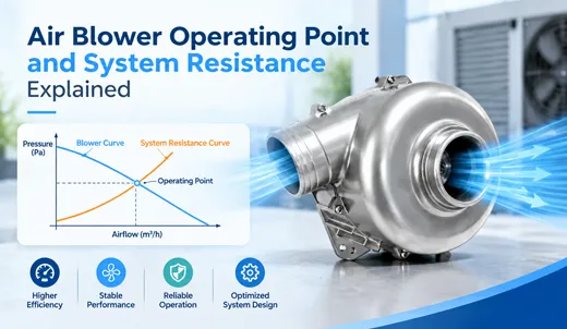
4. Operating Point & System Impedance Matching
Every brushless air blower exhibits a unique Peak Efficiency Point (PEP) along its Pressure vs. Flow (P-Q) curve. Operating a blower far away from its optimal pressure-flow zone causes fluid efficiency to plummet. Engineers must select a blower model whose sweet spot aligns precisely with their system's normal operating resistance rather than relying solely on free-air rating specs.
Efficiency & Performance Comparison: Brushed vs. TKFAN Brushless Air Blower
| Performance Parameter | Legacy Brushed Air Blower | TKFAN Brushless Air Blower |
|---|---|---|
| Peak Motor Efficiency | 55% – 70% | 75% – 90%+ |
| Partial-Load Efficiency | Poor (Linear voltage drop losses) | Excellent (PWM duty cycle modulation) |
| Mechanical Wear Sources | Carbon brush friction & commutator wear | Precision ball bearings only |
| Continuous Operational Lifespan | 1,000 – 5,000 Hours | 30,000 – 70,000+ Hours |
| Speed Control Capabilities | Limited (Voltage scaling) | PWM, 0-10V Analog, Closed-Loop PID |
| EMI & Electrical Noise | High (Arcing across carbon brushes) | Ultra-Low (Meets Medical EMC standards) |
| Tachometer & Safety Output | Rarely available | Integrated FG Pulse & RD Fault Alarms |
Real-World Case Study: TKFAN BA6560H24B-B in Medical Ventilators
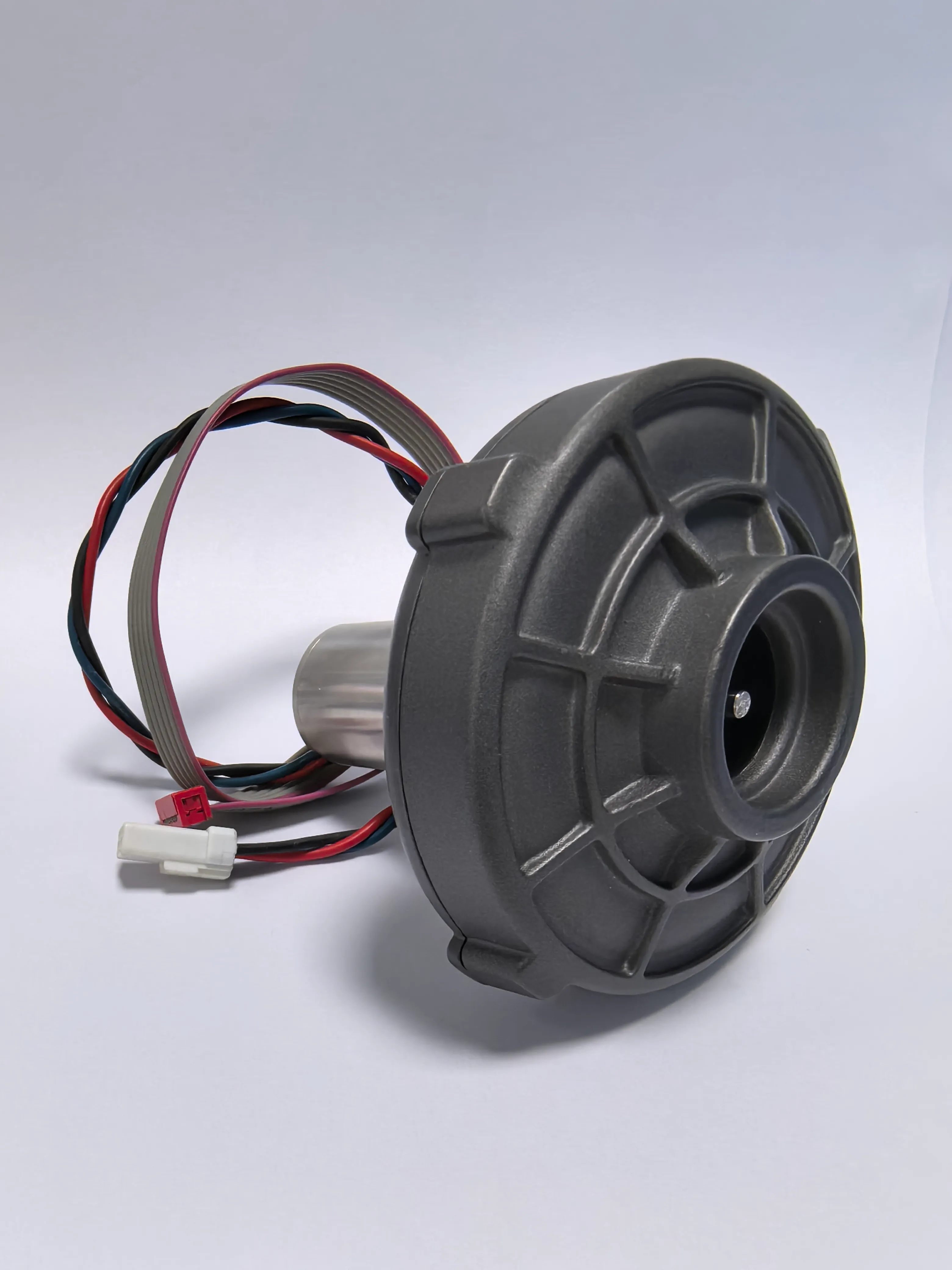
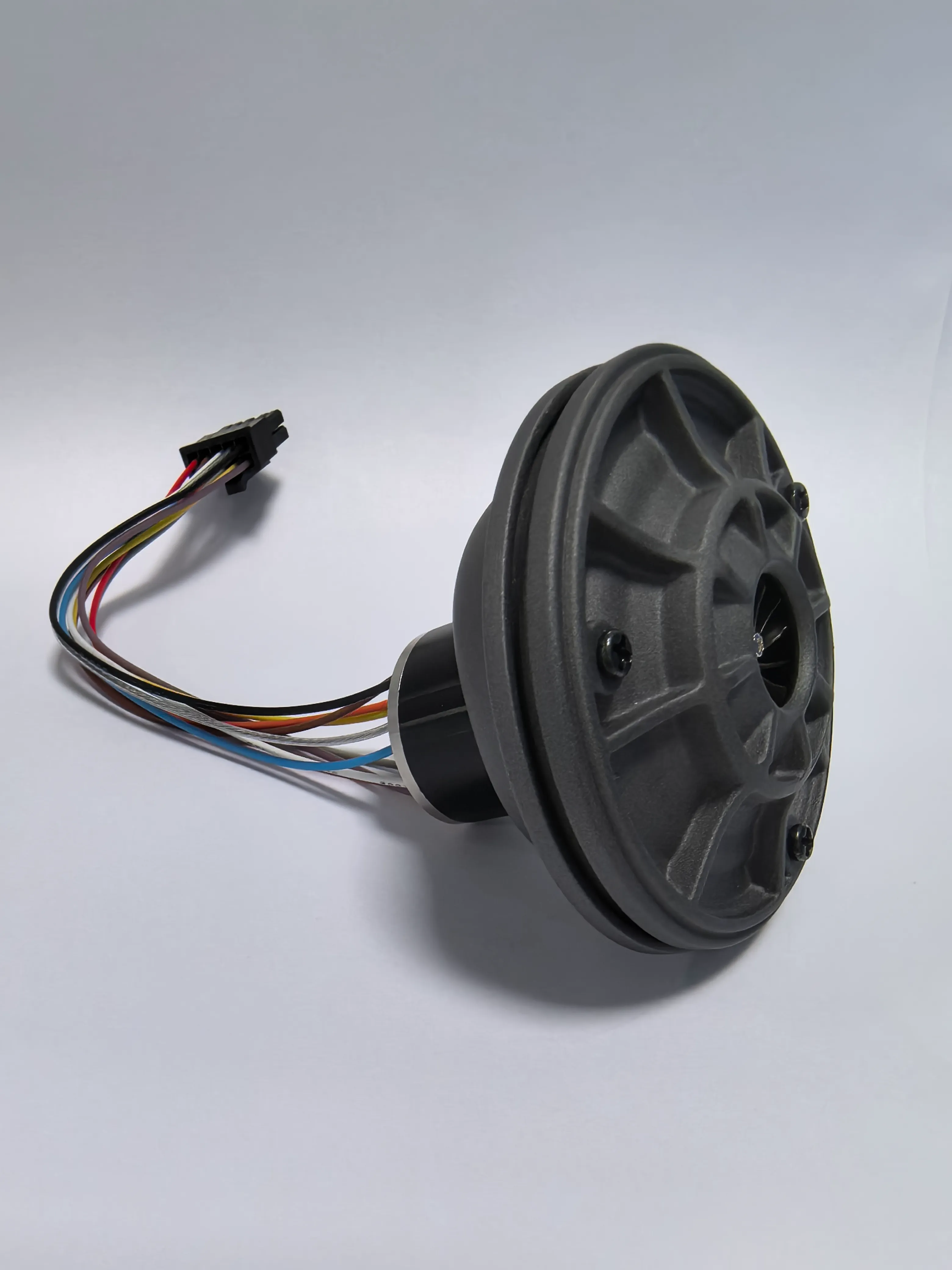
Medical intensive care ventilators represent one of the most demanding operational environments for a high-speed brushless air blower. Life-support ventilation equipment demands instantaneous velocity transitions, extremely high static pressure capability, quiet operation, and uncompromised continuous-duty reliability. The flagship TKFAN BA6560H24B-B air blower was specifically engineered to solve these rigorous engineering challenges.
Key design attributes of the BA6560H24B-B medical blower include:
- Dual Control Interface Flexibility: Supports both PWM and 0-10V analog input signals, allowing seamless integration into diverse medical control architectures.
- Low-Inertia High-Torque Rotor: Utilizes a lightweight, precision-balanced impeller coupled with an ultra-dense magnetic stator. This combination enables acceleration from idle to tens of thousands of RPM within milliseconds, ensuring precise synchronization with patient inhalation cycles.
- Medical-Grade Acoustic Dampening: Precision dynamic balancing limits mechanical vibration at maximum 67,000 RPM operational limits, preserving a quiet hospital ward environment.
- Closed-Loop FG Feedback Integration: Transmits real-time FG speed pulses to the host ventilator controller, ensuring stable target pressure delivery even as bacterial filters accumulate particulate resistance during long-term therapy sessions.
- Custom OEM Modifications: TKFAN offers custom voltage windings (5V/12V/24V), customized wiring harness lengths, specialized medical-grade connectors, and tailored mounting flanges. Qualified OEM engineering projects can receive custom prototype samples in as fast as 48 hours.
Common Engineering Mistakes in Blower Selection & Control
Even experienced engineering teams can encounter unexpected system degradation during device integration. Avoid these common implementation mistakes:
- Selecting Blowers Based Solely on Free-Air CFM Specs: Free-air airflow ratings reflect zero static backpressure. In real-world enclosures with tight ducts and HEPA filters, actual airflow drops significantly. Always evaluate the full P-Q performance curve of the TKFAN air blower.
- PWM Input Frequency Mismatch: Injecting a PWM control frequency outside the blower driver’s specified input range causes audible switching whine, erratic velocity oscillations, and driver efficiency drops. Always consult the product datasheet for verified PWM carrier frequency ranges.
- Operating Open-Loop Without Utilizing FG Feedback: Omitting tachometer tracking leaves the blower vulnerable to speed drift caused by thermal expansion, supply voltage variations, or filter clogging.
- Oversizing the Blower Unit: Specifying an oversized blower that constantly operates at low PWM duty cycles wastes board space, introduces unnecessary mass, elevates low-speed noise, and operates far outside the peak aerodynamic efficiency window.
- Ignoring System Duct Aerodynamics: Placing sharp 90-degree elbows, restrictive intake grilles, or undersized tubing immediately upstream or downstream of the blower inlet causes severe flow separation, ruining total system efficiency regardless of motor quality.
Technical Frequently Asked Questions (FAQ)
For critical medical devices like ventilators and CPAP machines, a closed-loop PID control architecture utilizing PWM speed input paired with Hall-effect sensor rotor position detection and FG tachometer feedback is strongly recommended. This guarantees precise dynamic response, high system stability under varying airway resistance, and superior partial-load energy efficiency.
Not necessarily. Every TKFAN air blower has a specific high-efficiency operating point determined by its aerodynamic P-Q curve. While ultra-high-speed models sacrifice minor peak electrical efficiency to overcome steep static pressure, their overall system efficiency remains optimized when operated within their intended pressure-flow design window.
While lowering the primary VDC supply line will reduce fan speed, it is not recommended as a primary speed control method. Doing so degrades motor torque, compromises internal driver logic stability, and lowers system efficiency. Instead, use the dedicated PWM or 0-10V analog speed control line provided on the driver board.
Dust accumulation increases system static backpressure, shifting the operating point along the fan's pressure-airflow curve. In open-loop control configurations, this added aerodynamic load causes motor speed drift. Implementing closed-loop PID control using the FG pulse output allows the driver to automatically increase duty cycle and maintain target RPM.
The primary causes of premature failure include continuous operation above rated current limits, excessive ambient temperatures, inadequate intake filtration causing impeller unbalance, severe mechanical vibration, and operating without locked-rotor protection enabled.
Hall-sensor control relies on physical magnetic sensors inside the stator for absolute rotor position detection, delivering instant startup torque and smooth performance under high backpressure. Sensorless control estimates rotor position via back-EMF, offering lower BOM cost but reduced reliability during zero-speed startup against steep static resistance.
Even if the BLDC motor achieves 90% electrical efficiency, poor impeller or volute aerodynamics can cause severe turbulence, flow separation, and recirculation losses, dropping the overall blow system efficiency to under 40%. Precision CFD-matched airflows are critical for high static pressure generation.
PWM control operates motor drive MOSFETs in high-frequency switching states rather than dissipative linear regions. This preserves maximum motor torque at low RPM, eliminates excess heat generation on the controller board, and improves partial-load energy efficiency.
The RD signal serves as a dedicated locked-rotor alarm. If an external object stalls the impeller or a bearing fails, the RD line switches state, triggering the main system CPU to cut power immediately to prevent thermal overload and catastrophic coil burnouts.
For qualified OEM engineering projects requiring voltage adjustments, custom wiring harness lengths, special connectors, or specific firmware tuning, TKFAN can deliver functional prototype samples in as fast as 48 hours.
Conclusion
Mastering the fundamentals of brushless air blower motor control and system efficiency is essential for hardware engineers designing modern medical ventilators, industrial equipment, analytical instruments, and high-reliability cooling systems. Compared to outdated brushed fans, integrating a premium TKFAN brushless air blower alongside optimized PWM speed control, closed-loop PID firmware execution, and hardware fault diagnostic feedback unleashes uncompromised mechanical lifespan and fluid performance.
Total system efficiency is determined by the combined performance of BLDC electromechanical winding design, drive switching efficiency, precision bearing mechanics, and CFD-optimized aerodynamics. Models like the flagship TKFAN BA6560H24B-B air blower prove that precision-engineered blowers deliver optimal static pressure conversion, whisper-quiet operation, and low energy consumption under demanding continuous-duty applications.