

Understanding Air Blower Operating Point & System Resistance: The Complete Engineering Guide
When engineering advanced hardware—ranging from medical ventilators, CPAP devices, and automotive ADAS sensor cleaning systems to compact industrial particle counters and smart home electronics—selecting the correct blowers is pivotal. A common pitfall occurs when engineers choose an air blower solely based on maximum airflow (CFM/LPM) or peak static pressure listed on a manufacturer datasheet. Once integrated into a tight enclosure, real-world performance often disappoints: airflow drops drastically, acoustic noise spikes, motors overheat, and bearings fail prematurely.
The root cause of these failures is a fundamental misinterpretation of fluid dynamics—specifically, the relationship between the air blower operating point and system resistance (system impedance). An air blower cannot perform inside a complex enclosure as it does during free-air laboratory testing. The true operating state is determined by the exact balance between the blower's pressure-delivery capability and the internal airflow resistance of your device.
This comprehensive guide explores the aerodynamic mechanics, mathematical laws, precise calculation methods, and optimization techniques needed to target the ideal TKFAN air blower performance curve. By mastering the TKFAN air blower operating point, design engineers and procurement specialists can eliminate field failures, minimize acoustic profiles, reduce power consumption, and extend product lifespans.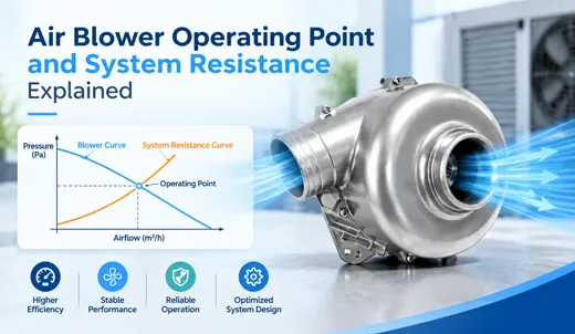
1. What Is an Air Blower Operating Point?
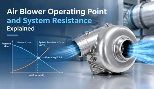
The air blower operating point (also known as the duty point or working point) is the exact coordinate on a P-Q (Pressure vs. Flow) performance chart where the airflow output curve of the blower intersects the internal system resistance curve of the target equipment. This single intersection simultaneously dictates three real-world operational values:
- Actual Delivered Airflow Volume: Measured in CFM (Cubic Feet per Minute), m³/h, or LPM (Liters per Minute).
- Actual Static Pressure Output: The pressure required to overcome total downstream and upstream airflow restrictions, measured in Pascals (Pa) or inches of water gauge (in. H₂O).
- Electrical Power Consumption & Speed: Motor power draw (Watts) and impeller RPM required under steady-state conditions.
When a TKFAN air blower is installed inside a sealed or semi-sealed chassis, it automatically operates at this specific equilibrium point. The device cannot deliver arbitrary airflow; it will stabilize strictly where the static pressure generated by the TKFAN air blower precisely balances the total static pressure losses across the fluid path.
Key Reference Points on the P-Q Curve
To analyze the air blower operating point, two theoretical extremes on the performance curve must be understood:
- Free Air Delivery Point (Qmax): System resistance is exactly zero. The air blower outputs maximum volumetric airflow with zero backpressure. Datasheet "Max Airflow" ratings reflect this condition. It occurs only when inlet and outlet are completely unobstructed.
- Shut-Off / Stall Point (Pmax): Airflow is completely blocked (Q = 0). The impeller builds maximum static pressure against a sealed barrier. While devices rarely run intentionally at shut-off, clogged filters or severe duct blockages can drive an air blower toward this state.
Crucial Rule: Commercial products never operate at Free Air Delivery or Shut-Off. Every functional device runs exclusively at a dedicated TKFAN air blower operating point situated between these two limits.
2. Demystifying System Resistance & Fluid Impedance
System resistance (or system impedance) represents the cumulative static pressure loss that air experiences when traversing an enclosure, including ducting, filters, heat sinks, nozzles, geometric bends, and internal components. Every obstacle in the fluid pathway strips kinetic energy from the airflow, converting it into pressure drops and turbulent noise.
The Quadratic Law of Fluid Mechanics
In forced-air thermal and pneumatic systems, airflow resistance follows the fundamental quadratic relationship (Square Law):
ΔP = K × Q²
Where:
- ΔP: Total system static pressure loss (Pa or in. H₂O).
- K: System impedance factor (a constant unique to your device's physical geometry).
- Q: Volumetric airflow rate (CFM, LPM, or m³/h).
This equation illustrates that system resistance scales non-linearly: if you double the required airflow (Q), system pressure losses (ΔP) quadruple. Consequently, minor geometric restrictions inside a compact enclosure drastically alter the air blower operating point, causing significant airflow reduction if pressure capability is insufficient.
Static vs. Dynamic System Impedance
| Impedance Type | Physical Causes | Impact on TKFAN Air Blower Operating Point |
|---|---|---|
| Fixed Static Resistance | Permanent duct geometry, casing walls, fixed vent grilles, heat sink fin density, permanent nozzle orifice sizes. | Establishes the initial baseline system resistance curve during factory assembly. |
| Variable Dynamic Resistance | Dust accumulation on HEPA/CPAP filters, adjustable air valves, variable nozzle apertures, debris buildup. | Causes the resistance curve to steepen over time, shifting the TKFAN air blower operating point towards higher pressure and lower airflow. |
3. Curve Interaction: How Operating Points Are Established
To accurately project product performance, engineers overlay the negative-sloped performance curve of the TKFAN air blower with the positive parabolic curve of system resistance.
The physical intersection of these two curves dictates the exact working condition. If physical modifications occur—such as adding a higher-efficiency particulate filter—the system resistance factor (K) increases. The parabolic curve steepens, moving the air blower operating point to the left along the performance curve (higher static pressure, lower flow rate).
Conversely, enlarging vent apertures or smoothing sharp duct corners lowers the K-factor. The parabolic curve flattens, shifting the TKFAN air blower operating point to the right (higher flow rate, lower backpressure).
4. Critical Impact of the Operating Point on Blower Performance & Reliability
Selecting an air blower is not merely about ensuring the duty point lies somewhere below the maximum curve limit. The specific region where the air blower operating point resides determines efficiency, acoustic emissions, thermal stability, and mechanical life.
A. Best Efficiency Point (BEP)
Every centrifugal blower has a Best Efficiency Point (BEP) where mechanical energy conversion from the motor to aerodynamic fluid power is optimized. Engineering best practices dictate targeting a TKFAN air blower operating point within ±10% to 15% of the BEP.
- Thermal Control: Minimal heat dissipation from internal fluid turbulence, keeping motor windings cool.
- Acoustic Minimization: Low aerodynamic noise generation—critical for medical CPAP devices and home equipment.
- Battery Longevity: Lower current draw, extending operating time in portable and handheld devices.
B. Aerodynamic Stall & Surge Instability Zones
Operating an air blower near the high-pressure, low-flow region (far left of the curve) forces the impeller blades to operate past their stall angle. Fluid separates from the blade surface, triggering unstable aerodynamic surge. This results in:
- High-frequency tonal noise, whistling, and structural vibration.
- Pressure fluctuations that compromise flow measurement accuracy in particle counters and ventilators.
- Thermal overload in brushless DC (BLDC) motors due to reduced convective self-cooling.
- Accelerated bearing wear caused by unstable hydraulic radial loads.
C. Excessive Free-Air Operation (Far Right Zone)
If the TKFAN air blower operating point falls too close to the free-air delivery limit, aerodynamic blade tip turbulence increases, generating high broadband air noise. This usually indicates an oversized air blower for low-resistance applications.
5. Influence of PWM Speed Control on Operating Points
Modern high-performance centrifugal blowers, such as the TKFAN air blower line, incorporate Pulse Width Modulation (PWM) speed regulation along with Tachometer (FG) speed feedback. Adjusting PWM duty cycle scales motor RPM, generating a family of parallel P-Q curves.
Per the Fan Affinity Laws:
- Airflow (Q): Varies directly with speed.
- Static Pressure (P): Varies with the square of speed .
- Power Draw (W): Varies with the cube of speed .
Varying PWM shifts the air blower operating point along the fixed parabolic curve of the system resistance. While PWM speed control offers flexibility for dynamic airflow adjustment, it cannot correct an improperly matched blower whose pressure capability falls short of high system impedance.
6. Step-by-Step Practical Selection Methodology
To reliably achieve your desired performance, follow this structured selection protocol during early-stage prototyping:
- Define Functional Airflow Requirements: Determine necessary cooling or pneumatics performance (e.g., 30 LPM for medical therapy, 5 CFM for heat dissipation, 100 Pa for air knife purging).
- Calculate Total System Resistance: Sum all expected static pressure losses across filters, ducts, bends, and heat sinks. Always include a 15–25% safety margin to account for filter loading over time. This yields your target air blower operating point coordinates.
- Plot on TKFAN Datasheet Curves: Compare your calculated duty point against candidate models on the TKFAN air blower catalog. Ensure the point falls comfortably within the continuous operational region, close to the BEP.
- Account for System Effect Losses: Real-world installation effects—such as sharp inlet turns or outlet obstruction—increase local turbulence and effective system impedance. Adjust pressure requirements accordingly.
- Empirical Prototype Validation: Measure actual airflow and static pressure on physical prototypes using a calibrated flow chamber or differential manometer to confirm the true TKFAN air blower operating point.
7. Real-World Engineering Case Studies
Case Study 1: Medical CPAP & Ventilator Systems
A medical device manufacturer required stable pressure output under changing inhalation and exhalation resistance profiles. A standard compact blower stalled during peak inhalation resistance, producing excessive acoustic noise and pressure ripples.
Solution: By analyzing the dynamic dynamic resistance shifts, engineers selected a high-pressure, fast-response medical TKFAN air blower with a wide stable operating envelope. The adjusted TKFAN air blower operating point remained safely outside the stall zone across all patient breathing cycles, resulting in quiet operation and steady pressure delivery.
Case Study 2: Automotive ADAS Sensor Cleaning
An autonomous driving vehicle camera cleaning nozzle required high-velocity air pulses to shed rain droplets and dust. Early prototypes suffered from insufficient jet velocity due to underestimating nozzle resistance.
Solution: Recalculating nozzle flow dynamics identified a steep resistance curve . Transitioning to a high-pressure brushless DC TKFAN air blower moved the air blower operating point to the required pressure level, ensuring reliable cleaning performance under extreme weather conditions.
8. Common Mistakes in Blower Integration
- Selecting via Datasheet Free-Air Ratings: Assuming a 20 CFM rated blower will deliver 20 CFM inside a restrictive enclosure is a frequent point of failure.
- Ignoring Dynamic Resistance Growth: Failing to account for dirt loading on air filters drives the air blower operating point into the stall zone over months of field use.
- Over-Sizing Blowers Excessive Margins: Adding excessive safety factors forces the duty point toward the far right or requires severe PWM throttling, causing unnecessary acoustic noise and power consumption.
- Neglecting System Effect Distortions: Installing blower inlets directly against structural walls severely restricts air intake, shifting the operating point unpredictably.
9. Customization Services from TKFAN Engineering
Off-the-shelf fan options often fall short of hitting the exact Best Efficiency Point inside custom hardware enclosure designs. TKFAN offers comprehensive OEM and ODM customization services for the complete TKFAN air blower product line, helping engineers tailor aerodynamics directly to target system impedances.
Customizable Blower Parameters
- Custom BLDC Motor Windings: Re-tuning motor KV to shift P-Q performance curves precisely to your operating point.
- Impeller & Housing Modifications: Aerodynamic geometry adjustments to suppress stall noise and widen stable operating zones.
- Voltage Options: 5V, 12V, 24V, 48V DC, and AC variations tailored to portable battery or industrial supply rails.
- Ingress Protection & Environmental Guarding: IP55, IP68 waterproof coatings, dustproofing, and thermal hardening.
- Smart Control Protocols: Customized PWM curves, FG tachometer output, and RD lock-alarm signals.
10. Frequently Asked Technical Questions (Technical FAQ)
Q1: What exactly defines the air blower operating point?
A: The air blower operating point is the precise intersection coordinate on a P-Q graph where the blower's delivered pressure matches the total system resistance (static pressure loss) of the host equipment. It defines actual delivered airflow, static pressure, power draw, and noise level during operation.
Q2: Why does my TKFAN air blower deliver less airflow in my product than listed on its datasheet?
A: Datasheet maximum airflow ratings reflect unobstructed zero-resistance "Free Air" conditions. Once installed inside an enclosure, components like filters, ducts, and circuit boards create system impedance, establishing a functional TKFAN air blower operating point with lower airflow at a higher static pressure.
Q3: How does filter dirt accumulation affect the TKFAN air blower operating point over time?
A: Dust loading increases the filter's resistance factor (K-value), steepening the system resistance parabola. This forces the TKFAN air blower operating point to shift leftward along the performance curve, resulting in reduced airflow and increased system static pressure.
Q4: Can I alter the system resistance curve using PWM speed control?
A: No. PWM speed control changes motor RPM, which shifts the air blower performance curve up or down. The system resistance curve is defined solely by the physical geometry of your equipment. Adjusting speed moves the operating point along the existing system impedance curve.
Q5: What happens if the air blower operating point falls into the aerodynamic stall region?
A: Operating in the stall region leads to fluid separation off the impeller blades, causing high tonal acoustic noise, mechanical vibration, pressure instability, reduced motor cooling, and shortened bearing service life.
Q6: How do I calculate system resistance to find my required TKFAN air blower operating point?
A: Sum all individual static pressure drops across filters, heat exchangers, ducts, and nozzles at your target airflow volume using the equation . The calculated coordinate represents your target duty point.
Q7: What is the Best Efficiency Point (BEP) for a centrifugal air blower?
A: The BEP is the coordinate on the P-Q curve where the air blower achieves maximum electrical-to-aerodynamic energy conversion efficiency. Designing for an air blower operating point near the BEP minimizes noise, heat, and power consumption.
Q8: What are "System Effect" losses, and how do they impact the blower duty point?
A: System Effect losses occur when non-ideal installation conditions—such as sharp duct elbows or obstructions placed too close to the intake or outlet—distort air velocity profiles, creating uncalculated pressure drops that shift the duty point to the left.
Q9: How does TKFAN assist engineers in matching the ideal air blower operating point?
A: TKFAN offers custom motor winding tuning, specialized impeller designs, aerodynamic housing modifications, and empirical flow-lab testing to ensure your TKFAN air blower operates safely at its Best Efficiency Point.
Q10: Where can I review detailed performance curves for TKFAN centrifugal blowers?
A: Complete technical datasheets, CAD models, and P-Q performance curves across all standard and high-pressure micro blower models are available on the official TKFAN Air Blower Product Portal.
Conclusion
Thoroughly evaluating the air blower operating point alongside device system resistance is key to successful forced-air integration. Designing around realistic duty points—rather than unconstrained free-air values—allows engineers to maximize efficiency, reduce acoustic levels, and ensure long-term hardware reliability. Explore the full performance capabilities of the TKFAN air blower line or contact our technical engineering team to tailor a custom aerodynamic solution for your next project.