
Comprehensive Guide: How to Select DC Cooling Fans for OEM Equipment
In thermal management engineering across industrial automation, medical diagnostic systems, telecommunications, energy storage systems (ESS), and rugged outdoor electronics, the humble DC cooling fan is far more than a simple commodity part. It acts as the primary heat mitigation defense mechanism for original equipment manufacturers (OEMs). A system's overall operational stability, Mean Time Between Failures (MTBF), acoustic profile, ingress protection rating, and compliance with international safety certifications are directly anchored to the selection of an appropriate OEM DC fan infrastructure.
Engineering departments often treat fan integration as an afterthought—selecting units based purely on superficial catalog parameters such as maximum volumetric airflow rate, nominal voltage, and physical frame dimensions. This methodology frequently leads to critical failures late in the product development lifecycle: unexpected thermal throttling, inadequate static pressure generation, premature bearing wear, ingress protection breakdown, and pulse-width modulation (PWM) control signal incompatibilities. Resolving these oversights post-production inevitably results in costly design revisions, assembly line halts, and expensive warranty liabilities.
The global emphasis on energy efficiency underscores the need for optimized thermal design. According to the International Energy Agency (IEA) Data Centre Energy Outlook 2025 report, annual worldwide energy consumption by data processing and computing infrastructure reached 485 Terawatt-hours (TWh) in 2024 and is projected to expand dramatically by 2030. Within unoptimized facility enclosures, active thermal management consumes over 30% of total system electrical draw. Even within highly optimized supercomputing nodes, thermal management consumes up to 7% of total power. Correctly implementing a high-efficiency TKFAN DC cooling fan directly minimizes long-term operational costs and parasitic power losses for OEM clients.
This comprehensive engineering manual provides a structured, multi-variable framework for selecting a TKFAN OEM DC fan. It covers thermal load calculations, P-Q performance curves, system voltage architectures, structural fan dynamics, bearing lifespans, ingress protection, digital control feedback, and environmental stress testing. For detailed product specifications or tailored engineering consulting, explore the full product portfolio at the TKFAN Official DC Fan Engineering Hub.
1. Accurate Thermal Load Calculation: The Foundation of Fan Selection
Rigorous thermal calculation must precede any component specification. Selecting a fan based on physical dimensions or peak catalog airflow alone introduces substantial operational risk. The baseline volumetric airflow requirements for an electronic enclosure are defined by the standard heat dissipation equation:
Metric System Formula (m³/h):
Q ≈ 3.0 × P / ΔT
Where Q represents the required volumetric airflow in cubic meters per hour (m³/h), P is the total dissipated internal power in Watts (W), and ΔT represents the maximum permissible internal temperature rise above ambient in Kelvin or Celsius (°C).
Imperial System Formula (CFM):
CFM ≈ 1.76 × P / ΔT_F
Where CFM represents Cubic Feet per Minute and ΔT_F represents temperature differential in degrees Fahrenheit (°F).
This mathematical simplification aligns with international thermal estimation frameworks, such as the IEC 60890:2019 standard for temperature-rise assessment in low-voltage switchgear and controlgear enclosures. Consider a practical industrial OEM scenario: an energy storage battery management cabinet dissipates 120 W of internal waste heat, with a strict thermal boundary requirement limiting internal temperature rise to ΔT = 15 K. Applying the standard thermodynamic formula yields an initial requirement:
Q = 3.0 × 120 / 15 = 24 m³/h (approx. 14.1 CFM)
Critical Engineering Distinction: This calculated value represents the required airflow under ideal, unobstructed open-air conditions. It does not reflect real-world operation inside an enclosure. Internal component density, circuit boards, cabling arrays, intake filters, and structural baffles create internal system resistance (static pressure). As backpressure increases, delivered airflow drops below nominal open-air catalog ratings. Relying entirely on nominal values without accounting for system impedance remains one of the primary causes of system overheating during pre-production verification.
The impact of operating off-design is detailed in official regulatory frameworks, including the European Commission Regulation (EU) No 327/2011 implementing Directive 2009/125/EC for fan eco-design requirements. Studies show that when a DC cooling fan operates away from its Best Efficiency Point (BEP) due to excessive unexpected backpressure, overall aerodynamic efficiency can drop by up to 45%. This reduction increases acoustic output and parasitic power draw while accelerating thermal degradation of the motor windings.
2. Deciphering the P-Q Performance Curve to Prevent System Underperformance
The Pressure vs. Volumetric Airflow (P-Q) characteristic curve is the essential engineering document for evaluating a TKFAN DC cooling fan. Provided by high-tier manufacturers, the P-Q diagram illustrates the relationship between static pressure and airflow delivery across a fan's operational range.
- Maximum Airflow Point (P=0): Located at the far-right origin of the horizontal axis. This represents open-air flow under zero static backpressure.
- Maximum Static Pressure / Stall Point (Q=0): Located at the top of the vertical axis. This represents absolute shut-off pressure when airflow is fully obstructed.
- System Operating Point: The exact point where the specific system resistance curve intersects the fan's P-Q curve. This indicates the actual delivered airflow inside the enclosure.
The operational goal when integrating an OEM DC fan is to position the system operating point within the high-efficiency peak zone of the P-Q curve—typically between 40% and 75% of maximum static pressure capability. Operating too close to the static pressure stall region induces boundary layer separation along the impeller blades. This condition triggers aerodynamic stall, which increases acoustic noise, elevates motor temperature, and destabilizes system thermal performance. Conversely, operating near zero static pressure leaves no margin for dust accumulation on air intake filters over time.
Tier-1 manufacturers provide verifiable P-Q performance data curves, voltage-scaling plots, acoustic power distributions, and thermal derating profiles. Integrating a fully documented TKFAN DC cooling fan into computational fluid dynamics (CFD) packages such as Ansys Icepak or Simcenter Flotherm enables thermal design teams to model system impedance accurately and optimize layout topologies before tooling production molds.
3. Voltage System Selection: 12V, 24V, and 48V DC Architectures
Selecting the optimal operating voltage for an industrial DC cooling fan involves balancing overall electrical efficiency, wire harness cross-sections, electromagnetic compatibility (EMC), and internal power rail layouts.
| Nominal Voltage | Primary Application Fields | Key Engineering Advantages | Design Considerations |
|---|---|---|---|
| 12V DC | Medical diagnostic devices, desktop instrumentation, automotive sub-assemblies, mobile platforms. | Broad component availability, lower step-down requirements from common low-voltage power supplies. | Higher current draw for a given wattage requires larger wire gauges; susceptible to voltage drops over long runs. |
| 24V DC | Industrial automation controllers, energy storage inverters, outdoor enclosures, power conversion systems. | Reduces current draw by 50% compared to 12V systems, lowering line losses; directly compatible with standard industrial 24V DC bus architectures. | Optimal balance of safety, thermal performance, and electrical footprint. Serves as the primary standard for industrial OEM designs. |
| 48V DC | Telecommunication base transceiver stations (BTS), enterprise servers, high-density data center racks. | Minimizes copper footprint and line loss across high-wattage arrays; maximizes motor efficiency at high operational speeds. | Must comply with strict safety isolation standards, such as the ETSI EN 300 132-2 standard for telecommunication -48V power interfaces. |
Relying on buck converters to adapt an incompatible fan voltage into an existing system architecture introduces extra failure points and parasitic power losses. Selecting a natively matched voltage configuration within the TKFAN DC cooling fan family optimizes system efficiency and simplifies regulatory safety compliance.
4. Axial vs. Centrifugal Fans: Matching Structural Aerodynamics to System Geometry
Improperly matching fan geometry to system resistance is a common pitfall in custom enclosure development. Understanding the aerodynamic trade-offs between axial and centrifugal designs ensures efficient air delivery through internal component layouts.
Axial Flow DC Fans
In an axial DC cooling fan, air enters and exits parallel to the central rotational axis of the motor shaft. Axial fans generate high volumetric airflow under low-to-medium static pressure conditions. They are ideal for open enclosures with minimal airflow obstruction, such as unencumbered heat sinks or direct ventilation ports. Their compact profile enables straightforward surface mounting on external cabinet walls.
Centrifugal DC Blowers
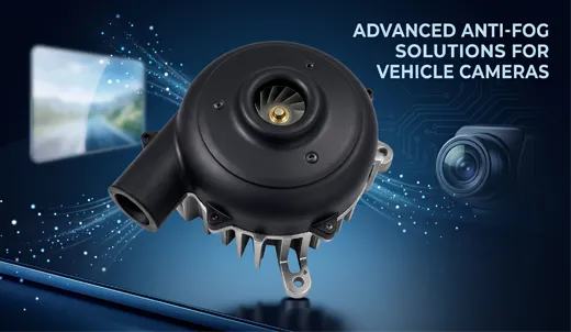
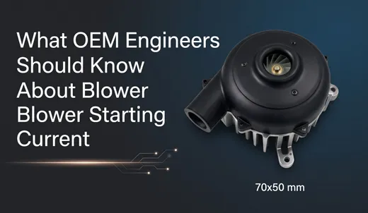
Centrifugal units (blowers) pull air in axially through the center inlet and accelerate it radially outward at a 90-degree angle using internal impeller blades. The centrifugal action creates high static pressure capability, enabling air to overcome tight system impedances caused by dense PCB stacks, bent ducting, heat exchangers, or high-efficiency particulate air (HEPA) filters. Advanced TKFAN OEM DC fan designs offer both forward-curved and backward-curved impeller configurations. Backward-curved impellers deliver higher hydraulic efficiency, reduced power consumption, and lower acoustic signatures under continuous high-pressure conditions.
5. Bearing System Specifications: Determining Real-World MTBF
The mechanical bearing system is the primary factor limiting the continuous operational lifespan of a DC cooling fan. Bearing endurance parameters are specified in accordance with the ISO 281:2007 standard for rolling bearings dynamic load ratings and life rating calculation, which defines the L10 life metric—the operational threshold reached by 90% of a sample lot before early fatigue failures manifest.
- Sleeve Bearings: Utilizing porous oil-impregnated sintered bronze, sleeve bearings offer an economical, low-noise solution for short-duty-cycle consumer electronics operating near ambient temperatures (25°C). However, elevated temperatures accelerate lubricant evaporation and oxidation, causing rapid wear, increased acoustic noise, shaft seizure, and a typical L10 rating below 20,000 hours.
- One-Ball, One-Sleeve Bearings: A hybrid construction combining a precision steel ball bearing on the high-load front side with a sleeve structure on the rear. This design offers a cost-effective compromise, extending the baseline L10 lifespan to approximately 40,000 hours at moderate operating temperatures.
- Dual Precision Ball Bearings: The industry standard for high-reliability medical, industrial, and automotive applications. Incorporating two micro-grooved, shield-sealed steel or ceramic ball bearing assemblies, dual-ball systems maintain low friction, high dynamic balance, and resistance to radial and axial loads. They withstand extreme thermal cycling (-40°C to +85°C) and consistently achieve certified L10 lifespans of 70,000 to over 100,000 hours. Every premium TKFAN DC cooling fan designed for mission-critical applications utilizes dual precision ball bearings.
Engineering Life Derating Note: MTBF values published in standard catalog datasheets reflect ideal laboratory conditions (typically 25°C ambient, nominal voltage, clean air). For every 10°C rise in continuous operational temperature above 40°C, the expected lubricant life inside the bearing assembly is halved (Arrhenius thermal reaction law). Severe vibration, rapid thermal shocks, and elevated humidity further reduce effective operational lifespan. Thermal margins must be incorporated during component specification.
6. Ingress Protection (IP Code): Matching Environmental Hardening Standards
Industrial electronics deployed in outdoor, washdown, high-dust, or marine environments require sealed cooling units to prevent electrical shorts and mechanical failures. Protection levels are governed by the international standard IEC 60529:2013 Degrees of Protection Provided by Enclosures (IP Code).
| IP Protection Code | Dust Protection Level (1st Digit) | Water Ingress Protection Level (2nd Digit) | Typical Industrial Application Scenarios |
|---|---|---|---|
| IP55 | Dust protected; limits ingress of harmful deposits. | Protected against low-pressure water jets from any direction. | Standard factory automation cabinets, indoor industrial controllers, sheltered enclosures. |
| IP65 | Dust-tight; complete protection against solid contact. | Protected against water jets delivered by a nozzle from any angle. | Outdoor solar inverters, agricultural control units, mobile construction machinery. |
| IP68 | Dust-tight; complete seal against micro-particulates. | Protected against continuous submersion in water under specified hydrostatic pressures. | Maritime navigation systems, submerged pumping controls, severe washdown food processing lines. |
In low-cost fans, ingress protection is often attempted using simple topical conformal coatings over assembled motor PCBs. Under ongoing thermal expansion and contraction, these superficial layers can micro-crack, allowing moisture and salt mist to enter the winding insulation. Authentic environmental hardening in a TKFAN OEM DC fan utilizes full vacuum-pressure epoxy encapsulation, hydrophobic stator coatings, sealed bearing cavities, and IP68-certified molded connector strain reliefs. This ensures long-term resistance to environmental degradation under severe operating conditions.
7. Advanced Speed Control and Diagnostic Signal Interfaces
Modern electronic cooling systems rely on active dynamic speed management to minimize power consumption, reduce acoustic footprint, and maintain consistent internal operating temperatures. Standard 2-wire fixed-voltage designs are increasingly replaced by 3-wire and 4-wire intelligent digital control interfaces.
Pulse-Width Modulation (PWM) Input
High-efficiency thermal architectures utilize a open-collector 5V or 3.3V logic PWM signal (typically operating between 21 kHz and 28 kHz) to regulate fan speed without altering the main DC supply voltage. Varying the duty cycle adjusts rotational speed from maximum down to a zero-speed state or minimum sustained RPM. This approach avoids the electrical efficiency losses, thermal dissipation issues, and torque dropouts associated with traditional linear voltage regulation.
Frequency Generator (FG) Tachometer Output
The FG signal (also known as a tachometer output) provides a square-wave digital output pulse generated by internal Hall-effect sensors. Producing 2 pulses per motor revolution, this interface allows system microcontrollers to continuously monitor real-world rotational speed. If an obstruction or bearing failure causes speed to drop below a pre-set threshold, the system host can trigger diagnostic alerts or controlled shutdowns to prevent overheating.
Rotation Detector (RD) Alarm Output
The RD signal acts as a binary status flag for critical safety monitoring. During normal rotation, the signal remains driven to a logic Low state. If the impeller stalls or experiences a mechanical block, the circuit switches to a high-impedance logic High state, triggering an immediate emergency alarm to the host system.
Configuring customized PWM response profiles, low-duty-cycle minimum speeds, custom pulse counts, and specific open-collector pull-up values within a tailored TKFAN DC cooling fan simplifies hardware integration with host microcontroller platforms.
8. OEM Customization Checklists: Defining Engineering Parameters
Transitioning from initial engineering samples to volume manufacturing requires a complete set of documented mechanical, electrical, and environmental specifications. Utilizing a standardized requirements checklist prevents design revisions and speeds up sample development cycles.
Comprehensive Engineering Customization Checklist:
- Dimensional & Physical Constraints: Outer frame length, width, thickness (mm), mounting hole spacing, hole diameter (counterbored vs. smooth), impeller blade profile.
- Electrical Specification Boundaries: Nominal input voltage (VDC), operating range tolerance (e.g., 18V to 30V DC), maximum running current (A), maximum startup inrush current, insulation resistance (minimum 10MΩ at 500V DC per IEC 60060).
- Aerodynamic Target Metrics: Minimum volumetric airflow at target system static pressure operating point, absolute maximum allowable acoustic pressure level (dBA measured per ISO 3744 at 1 meter).
- Cable & Connector Interfaces: Lead wire length (mm), wire gauge (AWG rating), insulation type (UL1007, UL1430, TEFLON), exact connector housing part number (e.g., JST, Molex, AMP, Hirose, IP67 Waterproof Circular).
- Control & Telemetry Options: PWM frequency range (kHz), active high/low logic, minimum duty cycle lock, FG pulse output, RD alarm logic, open-collector vs. push-pull output topologies.
- Environmental Hardening Standards: Operating temperature envelope (-40°C to +85°C), storage limits, relative humidity exposure, target IP rating (IP54 to IP68), salt spray resistance (IEC 60068-2-11), shock/vibration compliance (MIL-STD-810G).
- Regulatory & Compliance Documentation: Required safety marks (UL, cUL, TUV, CE), environmental standards (RoHS Directive 2011/65/EU, REACH EC 1907/2006 compliance), target MTBF per Telcordia SR-332 or ISO 281 L10 models.
9. Verification Protocol: Sample Qualification and Incoming Inspection
Validating an OEM DC fan requires a structured testing approach across three distinct stages to ensure design performance and production batch consistency:
Stage 1: Design Verification Testing (DVT)
Initial prototype samples must be installed into complete, functional system enclosures rather than tested on an open workbench. DVT evaluates real-world thermal performance, component temperature profiles, internal pressure distribution, acoustic levels, and PWM response curves under worst-case thermal loads and maximum ambient operating temperatures.
Stage 2: Reliability and Environmental Stress Screening (ALT/ESS)
To verify long-term reliability before committing to production tooling, sample units undergo accelerated life testing (ALT), thermal shock cycling (-40°C to +105°C), high-humidity aging (85°C / 85% RH for 1000 hours), salt mist exposure, and multi-axis sinusoidal vibration testing per standard IEC 60068 frameworks.
Stage 3: Production Validation Testing (PVT) & Quality Control
Pre-production pilot runs (typically 50 to 500 units) validate manufacturing consistency and component tolerances across production lots. Standardized incoming quality control (IQC) protocols specify testing parameters for static current draw, free-air rotational speed (RPM), FG signal frequency, dielectric withstand voltage (hipot testing), dynamic balance, and acoustic signature consistency.
10. Evaluating DC Fan Suppliers: Manufacturer Direct vs. Distributor Channels
Selecting an appropriate supply chain partner is just as important as choosing the right technical specifications. OEM procurement teams must weigh the operational trade-offs between component distributors and direct manufacturing sources:
| Evaluation Dimensions | Third-Party Commercial Distributors | Direct OEM Manufacturer (e.g., TKFAN Direct) |
|---|---|---|
| Customization Flexibility | Strictly limited to off-the-shelf standard SKUs; no custom wire lengths, custom PWM curves, or structural modifications. | Full engineering customization: tailored impellers, custom PCB layout, specific connector terminations, and custom IP encapsulation. |
| Technical Support Depth | Generic datasheet support; limited capability for deep CFD thermal simulations or root-cause failure analysis. | Direct access to thermal, mechanical, and electrical engineering teams; dedicated support for CFD modeling and design validation. |
| Supply Line Stability | Vulnerable to channel allocation changes, inventory fluctuations, and sudden component obsolescence. | Direct production scheduling, long-term component availability guarantees, transparent product lifecycles, and traceable batch quality control. |
| Total Cost Structure | Includes distribution markups; higher unit costs on mid-to-high volume production runs. | Optimized factory-direct pricing, direct volume scaling tiers, and lower long-term procurement overhead. |
High-capability manufacturing partners maintain certified wind-tunnel testing facilities compliant with AMCA 210 standards, automated dynamic balance systems, environmental testing chambers, and full trace-level quality control. Explore complete direct OEM engineering capabilities and product lines at the TKFAN Official DC Fan Hub.
11. Common Pitfalls in OEM Thermal Management Selection
- Relying Solely on Catalog Airflow Ratings: Selecting a fan based only on zero-backpressure airflow specs without evaluating the system's operating point on the P-Q curve leads to unexpected thermal issues once installed in dense enclosures.
- Ignoring Ambient Temperature Effects on Lifespan: Assuming published 25°C room-temperature MTBF specs apply to sealed, high-temperature industrial cabinets leads to premature field failures.
- Misjudging Ingress Protection Construction: Using standard fans with superficial conformal coatings in high-humidity or outdoor environments instead of fully encapsulated IP68 units causes premature electrical failure.
- Using Axial Fans in High-Impedance Systems: Installing low-pressure axial fans behind dense dust filters or heat exchangers causes aerodynamic stall, high acoustic noise, and inadequate cooling flow.
- Overlooking Electromagnetic Interference (EMI): Failing to specify proper EMC filtering in high-power brushless fan drivers can introduce electrical noise into sensitive analog sensors or communication buses.
- Omitting Thermal Safety Margins: Designing thermal management systems without a 15% to 25% airflow safety margin leaves no buffer for filter dust buildup, component aging, or ambient temperature spikes.
12. Frequently Asked Technical Questions (Technical FAQ)
Q1: Should my OEM industrial design utilize a 12V or 24V DC cooling fan architecture?
Matching the system's primary DC power bus is generally recommended. For industrial control cabinets, outdoor enclosures, and automation systems, 24V DC is preferred. A 24V fan draws 50% less current than a 12V unit of equivalent wattage. This reduces line drop over longer wiring runs, minimizes copper gauge requirements, improves overall electrical efficiency, and integrates natively with standard 24V industrial supply rails. 12V fans remain ideal for compact, low-voltage medical devices and portable instruments.
Q2: How do I quickly determine whether to specify an axial fan or a centrifugal blower?
Use an axial fan for low-impedance configurations with open airflow paths, minimal filtering, and large exhaust vents where high volumetric airflow (CFM) is required at low static pressure. Specify a centrifugal blower when airflow must push through high system resistance—such as dense PCB stacks, narrow channels, HEPA filters, or long internal ducts—that require high static pressure to maintain consistent flow.
Q3: Is a 4-wire PWM cooling fan required to have an FG tachometer signal?
While technically independent, mission-critical OEM applications (such as medical diagnostics, telecommunication nodes, servers, and ESS battery racks) typically combine PWM speed control with FG speed feedback on 4-wire fans. PWM controls the motor speed dynamically based on thermal load, while the FG signal provides real-world rotational feedback to the host processor, triggering immediate safety protocols if a fan lock or failure occurs.
Q4: Can an IP68-rated DC cooling fan operate submerged in liquid indefinitely?
An IP68 rating verifies protection against continuous immersion in water under specified hydrostatic pressures per IEC 60529 standards. However, long-term continuous underwater operation requires careful evaluation of fluid density, chemistry, and seal materials. For specialized applications like direct fluid immersion cooling or harsh chemical exposure, consult with TKFAN engineers to verify material compatibility and mechanical seal designs.
Q5: What is the typical lead time for custom OEM DC fan prototypes and samples?
Standard modifications—such as custom wire lengths, specific electrical connectors, or modified PWM response curves on existing frames—typically ship within 3 to 7 business days. Fully customized projects involving new injection molds, proprietary impeller designs, or specialized motor windings generally require 30 to 45 calendar days for tooling, DVT sample production, and preliminary laboratory testing.
Q6: How does operating ambient temperature affect dual ball bearing L10 lifespans?
High-quality dual precision ball bearings typically achieve an L10 lifespan of 70,000 to 100,000 hours at a baseline ambient temperature of 25°C. According to standard Arrhenius thermal models, sustained operation at elevated temperatures degrades synthetic grease lubricants over time. As a rule of thumb, every 10°C increase in continuous operating temperature above 40°C reduces effective bearing lubricant life by approximately 50%.
Q7: What is the difference between open-collector and push-pull FG signal outputs?
An open-collector FG signal relies on an external pull-up resistor (connected to the host logic voltage rail, e.g., 3.3V or 5V) to generate a clean square-wave signal. This design protects host microcontrollers by decoupling fan internal voltages from the logic circuit. A push-pull output actively drives the signal high and low internally, eliminating the need for an external resistor, but it requires strict voltage matching between the fan's signal output and the host interface.
Q8: How does dust accumulation on intake filters alter fan requirements over time?
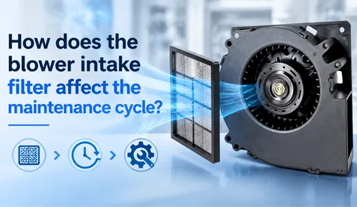
As dust builds up on air filters, system resistance increases, shifting the operating point upward along the fan's P-Q curve toward higher static pressure and lower airflow. If a fan lacks sufficient static pressure margin, delivered airflow can drop below required thermal thresholds, leading to component overheating. Incorporating a 15% to 25% static pressure safety margin during component selection helps ensure adequate cooling throughout maintenance intervals.
Q9: Why can electric fan motors induce unwanted EMI noise in surrounding circuitry?
Brushless DC fans use internal electronic switching circuits to drive stator windings. High-frequency switching can generate radiated and conducted electromagnetic interference (EMI) along power supply lines, potentially affecting nearby high-frequency communication buses or precision analog sensors. Selecting a high-grade TKFAN DC cooling fan equipped with integrated onboard EMC suppression filters (compliant with CE-EMC and FCC Class B limits) mitigates these interference risks.
Q10: What key metrics should be specified in an incoming quality control (IQC) protocol for fans?
An effective incoming inspection protocol should evaluate: 1) Physical dimensions and cable/connector integrity; 2) No-load running current and power draw at nominal voltage; 3) Free-air rotational speed (RPM); 4) FG square-wave pulse frequency and logic voltage levels; 5) Hipot dielectric withstand voltage (e.g., 500V AC for 1 minute); and 6) Startup minimum voltage thresholds to ensure consistent performance across production lots.