

How Does an Air Blower Work? Working Principle & Technical Guide
Published by TKFAN Thermal Management Engineering Team | Comprehensive Fluid Dynamics & Hardware Analysis
Introduction: Why Air Blower Working Principles Matter
If you are designing medical ventilators, automotive LiDAR cleaning units, high-density server enclosures, or airborne particle counters, you have undoubtedly encountered an air blower—frequently referred to as a centrifugal blower fan or miniature DC blower. Millions of engineers, procurement officers, and system designers search for "how does an air blower work" every year. However, most online engineering guides offer either overly abstract fluid dynamic equations or simplistic explanations that skip essential mechanical, electrical, and pneumatic interaction details.
An air blower is a specialized mechanical airflow device engineered to convert electrical energy into concentrated, high-pressure directional airflow. Unlike conventional axial cooling fans—which merely move large volumes of air at negligible static pressures—a centrifugal air blower is designed specifically to overcome high backpressure within restricted flow channels, dense HEPA filters, and tight internal enclosures. TKFAN designs and manufactures a broad spectrum of micro, brushless DC (BLDC), AC, waterproof, and medical-grade centrifugal blowers trusted by global OEMs. Mastering the operational principles of an air blower directly impacts your equipment's thermal stability, pneumatic efficiency, acoustic profile, and overall operating life.
This ultimate guide breaks down the full operational sequence of air blowers, dissects key internal components, illustrates the fluid dynamics of static pressure generation, compares blowers against axial fans and compressors, and evaluates structural design parameters.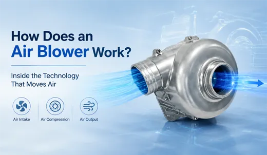
1. What Is the Core Purpose of an Air Blower?
1.1 Primary Functions of Centrifugal Air Blowers
At its fundamental level, a centrifugal air blower performs two primary mechanical tasks that axial fans simply cannot accomplish:
- Axial Air Intake: Air is drawn into the center inlet of the rotating impeller parallel to the motor shaft.
- Centrifugal Acceleration & 90-Degree Discharge: The high-speed impeller accelerates air particles outward using centrifugal force, converting kinetic velocity into effective static pressure, and discharging air at a 90-degree angle relative to the intake direction.
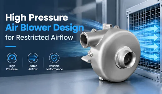
Standard axial fans push air linearly along the blade axis. When forced to push air through high-resistance pathways—such as narrow ducting, dense filtration beds, tight medical CPAP masks, or automotive sensor nozzle blowers—axial fans experience stalling, severe air backflow, and massive pressure loss. Air blowers excel at creating sufficient static head pressure to drive steady, unyielding airflow through highly constrained systems.
1.2 Critical Industry Applications Relying on Air Blowers
Thanks to their robust pressure-generating capabilities, centrifugal blowers serve as critical airflow drivers across diverse high-tech industries:
- Medical Technology: ICU ventilators, Continuous Positive Airway Pressure (CPAP) machines, neonatal respiratory care systems, and cleanroom particle counters.
- Automotive Electronics: Autonomous driving LiDAR sensor cleaning blowers, camera lens defogging systems, and luxury vehicle seat ventilation.
- Smart Appliances & Electronics: Portable air purifiers, air-cushion packaging machines, SMD hot-air soldering stations, and 3D printer cooling nozzles.
- Industrial & Telecom Systems: High-density rack server enclosures, telecom cabinet cooling, and IP-rated waterproof ventilation setups.
2. Step-by-Step Working Principle of an Air Blower
Every complete operating cycle of an air blower represents a precise energy conversion process: Electrical Input → Mechanical Rotational Energy → Centrifugal Kinetic Acceleration → Volute Pressure Conversion → High-Pressure Output.
Visual Flowchart of Blower Operation:
Power Supply → BLDC/AC Motor Drives Shaft → Impeller Rotation → Vacuum Intake at Hub → Radial Air Acceleration → Volute Expansion Chamber → Kinetic Energy Converts to Static Pressure → 90° Concentrated Air Discharge.
Step 1: Electrical Power Drives Motor Rotation
The sequence begins when electrical voltage (typically 5V, 12V, 24V, 48V DC, or 110V/220V AC) is applied to the blower winding circuit. In modern TKFAN blowers, a Brushless DC (BLDC) motor receives power, generating an alternating magnetic field that rotates the permanent magnet rotor. Because BLDC motors eliminate friction-prone carbon brushes, they deliver exceptional operational longevity, silent performance, and seamless Pulse Width Modulation (PWM) speed control.
Step 2: Negative Pressure Creation Draws Intake Air
As the impeller rapidly spins, air inside the hub area is thrown outward due to rotation. This displacement creates a localized low-pressure zone (vacuum) at the inlet eye. Ambient atmospheric pressure forces ambient air axially into the center opening of the blower housing. In micro blowers (e.g., 40x40x10mm units), bell-mouth contoured inlets are used to minimize inlet turbulence and maximize airflow smoothness.
Step 3: Centrifugal Force Accelerates Air along Impeller Blades
This is the defining mechanical principle that separates centrifugal blowers from axial fans. As air molecules enter the spinning impeller, curved blades trap the air and impart high rotational speed. Centrifugal force pushes the trapped air outward along the blade surfaces toward the outer periphery, much like water being sloshed to the edges of a spinning bucket. Mechanical energy from the motor transfers into the air, drastically boosting its kinetic velocity.
Step 4: Volute Scroll Converts Kinetic Velocity into Static Pressure
High-speed air exiting the blade tips enters the snail-shaped housing called the volute (or scroll). The cross-sectional area of the volute channel gradually expands along its spiral path toward the outlet. According to fluid dynamics principles (Bernoulli's Principle), as the channel expands, the velocity of the air decreases while its static pressure increases. By the time the air reaches the side discharge port, it has transformed into a high-pressure air stream oriented 90 degrees away from the inlet.
3. Key Components of an Air Blower Assembly
To fully grasp how an air blower functions, we must examine the internal structural components that make up a high-performance TKFAN centrifugal blower:
3.1 The Driving Motor (BLDC or AC)
The motor is the mechanical heart of the blower. Brushless DC (BLDC) motors dominate micro and medical blowers due to their high power density, integrated circuit control, and lifespan exceeding 50,000 to 70,000 hours of continuous duty.
3.2 The Impeller (Fan Wheel)
Mounted directly onto the motor rotor shaft, the impeller features engineered curved blades made from reinforced PBT plastics, aluminum alloy, or die-cast metal. Impeller blade geometries dictate airflow behavior:
- Forward-Curved Blades: Produce high airflow at lower rotational speeds; optimal for compact electronics cooling.
- Backward-Curved Blades: Deliver high energy efficiency and superior static pressure; ideal for medical CPAP units and industrial blowers.
- Radial Straight Blades: Generate maximum pressure head and excel in self-cleaning or particle-laden air environments.
3.3 The Volute Housing (Scroll Case)
The sealed spiral casing surrounding the impeller. Constructed from engineered polymers or aluminum alloys, its precisely calculated expansion ratio ensures optimal conversion of dynamic air pressure into static pressure while suppressing acoustic turbulence.
3.4 Precision Bearings & Circuit Boards
High-grade dual ball bearings stabilize the rotor shaft, maintaining ultra-tight clearances and suppressing vibration. Built-in PCB controllers manage motor commutation, thermal protection, PWM speed regulation, FG tachometer speed feedback, and RD lock alarms.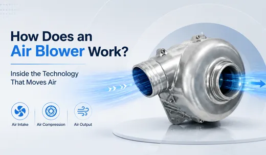
4. How Air Blowers Generate Airflow and Static Pressure
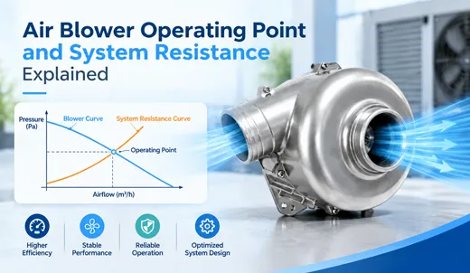
Understanding the distinction between airflow volume and static pressure is vital when evaluating air blower performance curves.
4.1 Airflow Volume Generation (CFM / m³/h)
Airflow volume measures the total bulk quantity of air moved per unit of time. In centrifugal blowers, volumetric flow rate is primarily governed by impeller rotational speed (RPM), total blade surface area, and inlet throat diameter. Increasing motor RPM linearly increases volumetric displacement.
4.2 Static Pressure Generation (Pa / mmH₂O)
Static pressure represents the potential energy stored in compressed air that enables it to push through system resistance (e.g., air filters, narrow ducts, heat exchangers). Static pressure is created in two distinct stages: first by the centrifugal force imparted by blade tip speed, and second by the fluid deceleration occurring inside the expanding volute scroll.
4.3 PWM Speed Control for Dynamic Pressure Adjustment
Modern DC air blowers utilize Pulse Width Modulation (PWM) signals to adjust motor speed on demand. When thermal or pneumatic sensors detect increased load, the system controller increases the PWM duty cycle, speeding up the impeller to generate elevated pressure and flow. During low-demand states, RPM decreases, saving power and minimizing operating noise.
5. Comparison: Air Blowers vs. Axial Fans vs. Air Compressors
System designers frequently evaluate whether an axial fan, a centrifugal blower, or an air compressor is best suited for their system. The comparison table below highlights their fluid dynamic differences:
| Parameter | Axial Cooling Fan | Centrifugal Air Blower | Air Compressor |
|---|---|---|---|
| Airflow Path | Straight through (Parallel to shaft) | 90-Degree Turn (Axial inlet, radial outlet) | Positive displacement or multi-stage compression |
| Pressure Ratio | Very Low (< 1.05) | Medium to High (1.1 to 1.3) | Extremely High (> 2.0 to 10+ bar) |
| Airflow Volume | High in open spaces | Balanced Volume & Static Pressure | Low Volumetric Flow Rate |
| Resistance Handling | Poor (Stalls easily against static head) | Excellent (Pushes through filters/ducts) | Unaffected by downstream duct resistance |
| Typical Uses | PC case ventilation, open radiators | Medical ventilators, CPAP, sensors, servers | Pneumatic tools, high-pressure industrial lines |
6. How Structural Design Parameters Impact Blower Performance
Every structural modification alters the performance metrics of an air blower. TKFAN offers comprehensive OEM/ODM customization based on these fluid dynamic variables:
- Impeller Blade Geometry: Shifting blade angles from forward-curved to backward-curved dramatically alters pressure curves and acoustic spectrums.
- Volute Expansion Angle: Oversized volutes reduce static pressure conversion, while undersized volutes create air choking and high turbulence noise. Advanced CFD (Computational Fluid Dynamics) modeling ensures optimal casing geometry.
- Motor Efficiency & Input Voltage: Higher voltage DC models (24V/48V) allow higher current efficiency for ultra-high-speed micro blowers running up to 30,000+ RPM.
- IP-Rated Ingress Protection: Conformal coating and fully potted stator resin seals (IP55/IP68) shield internal coils and PCB electronics from moisture and dust contamination without altering airflow efficiency.
7. Technical Frequently Asked Questions (Technical Q&A)
An axial fan blows air straight through parallel to its rotation axis, providing high airflow only in zero-resistance open environments. An air blower draws air axially into its center and hurls it outward at a 90-degree angle using centrifugal force, generating high static pressure to push air through restrictive filters, tight spaces, and complex ducting.
High-pressure blowers utilize ultra-lightweight, backward-curved impellers running at high rotational speeds (20,000+ RPM) driven by BLDC motors. The combination of intense centrifugal force and an aerodynamically tight volute scroll boosts static head pressure, allowing the blower to maintain precise, unwavering airflow through humidifiers, HEPA filters, and patient breathing tubes.
Yes. TKFAN industrial and medical-grade BLDC air blowers are engineered for continuous 24/7 operation. Equipped with premium dual-ball bearings, dynamic balancing, and brushless electronic commutation, these units offer an operational L10 lifespan exceeding 50,000 to 70,000 hours at elevated ambient temperatures.
Pulse Width Modulation (PWM) dynamically switches the motor's power supply on and off at high frequencies. By adjusting the duty cycle (e.g., from 20% to 100%), the system directly modulates motor RPM. As RPM increases or decreases, the centrifugal force generated by the impeller changes correspondingly, allowing real-time tuning of airflow rate and static pressure.
The FG (Frequency Generator/Tachometer) signal outputs a square wave pulse proportional to motor speed, allowing the system host to monitor RPM in real-time. The RD (Rotation Detection/Lock Alarm) signal alerts the host system if the blower impeller is locked or obstructed, triggering safety protocols in critical systems like server cooling or medical ventilators.
BLDC motors eliminate mechanical carbon brushes, preventing brush wear, carbon dust contamination, and electrical spark interference (EMI). This results in longer service life, whisper-quiet sound output, higher energy efficiency, and compliance with stringent medical and automotive safety standards.
Imbalanced impellers create mechanical vibration, excessive acoustic noise, and premature bearing wear. High-speed blowers undergo dual-plane electronic dynamic balancing during manufacturing to ensure rotational eccentric vibration stays within microscopic tolerances, delivering smooth operation and silent acoustic signatures.
Airflow loss and noise spikes are usually caused by severe inlet flow restriction, improper housing volute clearance, abrupt 90-degree duct bends near the outlet, or operating the blower near its pneumatic stall point on the performance curve. Proper fluid matching ensures optimal efficiency and low noise.
Yes. Outdoor automotive LiDAR, telecom, and industrial blowers utilize full vacuum epoxy potting techniques to seal the motor stator and internal electronics, achieving IP55, IP67, or IP68 ingress protection against direct water jets, moisture, and fine dust particles.
Absolutely. TKFAN specializes in custom OEM/ODM solutions. Engineers can tailor housing footprints, impeller geometries, operating voltages (5V-48V DC, 110V/220V AC), custom wiring harnesses, connector types, and acoustic profiles to meet exact client specifications.
Conclusion
Understanding how an air blower works empowers engineers and product designers to select the ideal forced-air cooling or ventilation setup for high-impedance applications. By converting rotational kinetic energy into static head pressure via centrifugal force and volute diffusion, blowers bridge the gap between low-pressure axial fans and ultra-high-pressure air compressors. Whether you require a miniature 5V micro blower for portable equipment or a high-speed BLDC blower for medical ventilators, TKFAN delivers customized fluid dynamic solutions designed for maximum reliability, optimal efficiency, and ultra-long service life.