

How Back Pressure Affects Air Blower Performance: An Engineering Guide
Design engineers selecting an air blower for medical ventilators, automotive sensors, compact electronics, or industrial machinery frequently rely on free-air flow ratings published on manufacturer datasheets. However, development teams often discover a stark discrepancy once the device is fully integrated: actual output airflow falls significantly short of laboratory ratings. In the vast majority of engineering scenarios, the primary cause of this airflow drop is system back pressure—also known as system static resistance or impedance.
Back pressure represents the opposing force an air blower must overcome to push air through filters, restrictive ducts, sharp elbows, tight enclosure spaces, or downstream processing components. Every physical component placed within the pneumatic pathway restricts airflow. High-efficiency particulate air (HEPA) filters, narrow tubing bends, sudden pipe contractions, densely packed printed circuit boards (PCBs), and accumulated dust over time contribute directly to system impedance. These factors generate static resistance that alters the baseline air blower performance, shifting the operating point away from ideal zero-resistance conditions.
Even premium brushless DC (BLDC) units cannot bypass the laws of fluid dynamics. Thoroughly understanding how system resistance reshapes TKFAN air blower performance allows engineering teams to prevent costly prototype failures, unexpected acoustic noise, motor overheating, and premature component fatigue. This comprehensive guide breaks down the physical mechanics of back pressure, analyzes P-Q performance curves, evaluates real-world application failures, compares axial fans with centrifugal blowers, and provides actionable design principles to optimize your TKFAN air blower selection for any demanding operating environment.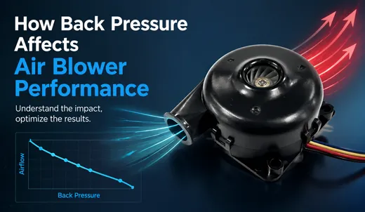
What Exactly Is Back Pressure in Blower Systems?
Before analyzing performance degradation, it is necessary to establish precise aerodynamic definitions. In forced-air systems, back pressure (or static pressure) is the total resistance opposing air movement at the discharge outlet of the unit. When an air blower forces air into a ducting network or sealed chamber, the air molecules collide with internal surfaces, encounter geometric restrictions, and experience friction along channel walls. This cumulative resistance creates a reverse pressure gradient acting directly against the impeller outlet.
To accurately evaluate equipment specifications, engineers must distinguish between two fundamental metrics:
- Free-Air Flow Rating: The maximum volume of air delivered per unit of time when the discharge outlet is completely open to ambient atmosphere (zero static pressure). This figure represents an idealized laboratory baseline and rarely reflects real-world operational environments.
- Operating Airflow Rate: The actual volumetric flow delivered inside a physical device. This value is strictly determined by the intersection of the air blower performance curve and the unique system impedance curve of the target application.
A common pitfall during hardware development involves designing thermal or pneumatic systems assuming free-air performance. Once air filters, heat exchangers, and protective grilles are installed, back pressure rises rapidly, causing the delivered airflow to plummet. Understanding this relationship explains why an air blower with impressive datasheet airflow specs may underperform inside a compact chassis.
System static resistance typically originates from four main sources:
- Ducting and Channel Geometry: Narrow internal diameters, excessively long pipe runs, 90-degree elbows, and sharp expansions or contractions create severe fluid drag and turbulence.
- Filtration Media: HEPA filters, foam dust screens, and hydrophobic medical membranes present high initial resistance. As dust and debris accumulate during operation, filter impedance rises continuously.
- Internal Component Obstructions: Dense PCB layouts, wiring harnesses, structural ribs, and heat sinks positioned directly within the airstream restrict flow channels.
- Lifecycle Degradation: Dust accumulation on impeller blades, clogged intake screens, and aging seals progressively increase total system back pressure over thousands of operating hours.
For precision equipment like medical ventilators, air quality monitors, and automotive LiDAR cleaning systems, accounting for lifecycle back pressure fluctuations is vital during early system architecture. Explore the full range of high-pressure miniature blowers on the official TKFAN air blower product page.
Understanding the Pressure vs. Flow (P-Q) Performance Curve
Every industrial and miniature air blower is defined by a Pressure-Flow (P-Q) performance curve. This diagram visually illustrates how static back pressure alters output airflow capacity across its entire operational spectrum. The horizontal axis represents volumetric airflow (CFM or L/min), while the vertical axis indicates static pressure capability (Pascals or inches of water gauge, in H2O).
Every P-Q curve contains two absolute operational boundaries:
- Free-Air Delivery Point : Maximum volumetric airflow output under zero back pressure.
- Shut-Off Pressure Point : Complete discharge blockage where airflow drops to zero, and the air blower generates its maximum possible static pressure (shut-off head).
Real-world operating points always lie between these two extremes. As downstream back pressure increases, the system operating point slides to the left along the P-Q curve. This movement results in reduced volumetric airflow alongside an increase in static pressure output. Evaluating high-pressure TKFAN air blower performance requires matching the blower's operational curve against calculated or measured system resistance curves.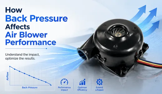
Standard axial fans exhibit steep performance drops when subjected to back pressure, quickly entering aerodynamic stall zones under moderate resistance. In contrast, centrifugal TKFAN air blower designs feature backward-curved or forward-curved impellers that maintain higher static pressure headers. This geometric advantage allows TKFAN air blower performance to remain stable and deliver continuous airflow even within high-impedance environments like HEPA-filtered enclosures.
Primary Ways Back Pressure Impairs Blower Performance
Subjecting an air blower to high back pressure triggers widespread secondary effects across the entire mechanical system. Beyond simple flow reduction, unmanaged static pressure affects electrical power consumption, thermal management, acoustic emissions, and aerodynamic stability.
1. Volumetric Airflow Reduction
The most immediate consequence of elevated static resistance is the drop in delivered air volume. Even moderate back pressure can reduce actual airflow to a fraction of the open-air specification. For example, a miniature medical air blower rated for 12 L/min under free-air conditions may deliver only 5 to 6 L/min when connected through a fine antibacterial filter and narrow patient tubing.
If your device relies on a strict airflow threshold—such as a particle counter, CPAP machine, or air-cushion packaging system—unexpected back pressure will prevent the end product from meeting functional specifications. Verifying full P-Q curves ensures that selected components satisfy airflow requirements at target operating pressures.
2. Motor Electrical Load and Thermal Strain
In BLDC motor-driven systems, operating under extreme back pressure alters the mechanical torque load on the shaft. Depending on impeller geometry (forward-curved, backward-curved, or radial), power consumption may spike or fluctuate wildly near shut-off conditions. When an air blower operates continuously against high resistance, reduced airflow over the internal motor housing diminishes self-cooling efficiency.
Elevated motor winding temperatures accelerate insulation breakdown, demagnetize internal permanent magnets, and degrade bearing lubricants. Over thousands of hours of continuous industrial operation, thermal stress induced by excessive back pressure substantially reduces overall service life. Engineered thermal dissipation channels inside high-efficiency TKFAN air blower units mitigate these thermal risks under heavy operational static pressures.
3. Elevated Acoustic Noise and Vibration
Exposing an air blower to excessive resistance disrupts smooth fluid dynamics inside the housing scroll. Near stall conditions, boundary-layer separation occurs along the impeller blades, causing localized airflow recirculation and turbulence. This phenomenon generates severe aerodynamic noise, dominated by low-frequency hums and broadband acoustic turbulence.
In noise-sensitive environments—such as hospital rooms, medical laboratories, or quiet vehicle cabins—back pressure-induced acoustic spikes can render a product non-compliant with noise standards. Selecting a TKFAN air blower with dynamic balancing and optimized blade geometry preserves quiet operation across varying pressure zones.
4. Aerodynamic Stall and System Instability
When static resistance approaches or exceeds the maximum pressure head capability of the impeller, the air blower enters aerodynamic stall. During stall, air fails to detach cleanly from the blade edges, leading to pressure oscillations, severe vibration, and unstable airflow delivery. Operating within the stall zone exposes bearings to uneven radial loads, inducing mechanical wear and potential driver electronics failure.
Real-World Applications: Impact of Back Pressure on TKFAN Air Blowers
Different commercial and industrial fields present unique pneumatic resistance challenges. The following application examples demonstrate how specialized engineering ensures consistent TKFAN air blower performance under adverse back pressure environments.
Medical Devices: Mechanical Ventilators & CPAP Systems
In positive airway pressure therapies, the air blower must deliver precise pressure and flow profiles through bacterial filters, humidification chambers, flexible tubing, and patient masks. Patient breathing cycles create dynamic back pressure fluctuations in real time. If static pressure response is insufficient, therapeutic delivery collapses. High-speed BLDC-driven medical blowers feature low-inertia impellers and closed-loop control to rapidly adjust speed, ensuring consistent TKFAN air blower performance despite changing circuit impedance.
Automotive ADAS Sensor Cleaning Modules
Modern autonomous and driver-assist vehicles rely on optical cameras and LiDAR units exposed to external weather conditions. Clean-air pulse systems use an ultra-compact air blower to blast high-velocity air across small nozzles to clear mud, rain, and debris. The tiny nozzle orifice creates instantaneous back pressure spikes. Custom heavy-duty blowers are constructed to withstand cyclic pressure pulses without experiencing mechanical fatigue or motor driver overload.
Cleanroom Particle Counters and Environmental Monitors
Air sampling equipment demands precisely regulated volumetric intake rates (e.g., exactly 28.3 L/min) to compute accurate particle concentrations. Air pulled through intake probes and internal sample chambers encounters significant resistance. Utilizing a high-static TKFAN air blower ensures that air sampling volumes remain stable, protecting measurement precision even as sample filters collect airborne particulate matter.
Industrial Air Cushion Packaging Machinery
Packaging machines use continuous-duty blowers to inflate protective air pillows at high production speeds. Pressurizing closed film channels creates continuous back pressure against the discharge port. Insufficient static pressure capacity yields under-inflated packaging cushions, compromising product protection during transit. Robust industrial blowers maintain continuous static pressure for reliable film inflation during multi-shift operations.
Comparing Performance: Centrifugal Blower vs. Axial Fan Under Back Pressure
Integrating the wrong fan architecture into a high-resistance system is a frequent system-level design error. Axial fans move air parallel to the impeller shaft, providing high volumetric flow rates in open environments but struggling against static resistance. Centrifugal blowers draw air axially and discharge it at a 90-degree angle, leveraging centrifugal forces to build substantial static pressure.
| Performance Metric | Standard Axial Fan | TKFAN Centrifugal Air Blower |
|---|---|---|
| Behavior under high back pressure | Rapid airflow drop; highly susceptible to immediate aerodynamic stall | Sustained airflow output; maintains steady pressure head |
| Optimal application context | Open chassis ventilation, low-resistance heat sinks | Ducted networks, fine filtration, tight enclosures, high impedance |
| Acoustic profile at maximum resistance | Sharp increase in broadband turbulent noise and stall hum | Controlled, predictable noise increase within stable pressure zone |
| Typical industry applications | PC case cooling, general cabinet ventilation | Medical CPAP, automotive sensors, sampling devices, packaging |
As detailed in the table above, applications involving high-density internal layouts or ducting networks require a specialized centrifugal unit. To review full technical specifications, access the complete TKFAN micro air blower series, including 12V, 24V, 48V, waterproof, and medical-grade models.
Engineering Strategies to Mitigate Back Pressure Performance Loss
While back pressure cannot be entirely eliminated in functional systems, applying sound engineering practices minimizes its negative effects on overall system efficiency and equipment lifespan.
1. Prototype System Impedance Early in Development
Avoid selecting blowers purely from static datasheet values. Build physical flow-test mockups containing true production filters, ducting configurations, and internal layout mockups. Use differential pressure transducers to measure exact system static pressure at target airflows. Use these measurements to select an air blower whose P-Q curve matches your operational requirements.
2. Maintain a Static Pressure Safety Margin
Ensure that your calculated maximum operating pressure (including worst-case scenarios like fully dust-clogged filters) does not exceed 50% to 65% of the blower's maximum shut-off static pressure rating. Keeping the operational point within the stable right-hand portion of the P-Q curve avoids aerodynamic stall, lowers acoustic signatures, and prolongs motor life.
3. Optimize Physical Airflow Paths
System designers can lower baseline static impedance by optimizing internal fluid mechanics:
- Increase internal duct cross-sectional areas whenever chassis space permits.
- Replace sharp 90-degree elbows with smooth, sweeping bends .
- Eliminate sharp internal transitions, burrs, and sudden duct expansions.
- Establish a regular filter replacement schedule to prevent excessive dust loading.
4. Utilize Closed-Loop Motor Control Functions
Advanced BLDC motor controls help mitigate back pressure variations over the equipment lifecycle. Premium TKFAN air blower designs support intelligent signal protocols:
- PWM Speed Control: Allows the main system controller to increase blower RPM as downstream pressure sensors detect filter clogging, maintaining constant airflow.
- FG Tachometer Feedback: Provides precise real-time rotational speed output, allowing diagnostic software to detect impedance changes.
- RD Alarm Output: Triggers safety alerts if high pressure or mechanical blockage causes motor lockup.
5. Request Custom OEM Aerodynamic Configurations
When off-the-shelf units cannot satisfy unique spatial, voltage, or pressure requirements, custom OEM modifications provide an efficient alternative. Customizing blade geometry, housing scroll profiles, motor winding configurations, and connector leads optimizes TKFAN air blower performance for unique system impedances. Customized prototype units can often be produced in short turnaround times for fast-track testing.
Frequently Asked Questions (Technical FAQs)
Conclusion
In real-world applications, back pressure is an unavoidable physical factor that directly affects air blower performance. Static resistance lowers output airflow, shifts thermal profiles, alters acoustic signatures, and influences long-term motor reliability. Relying solely on free-air datasheet metrics often results in performance gaps during system integration.
By measuring system impedance during early prototyping, applying a 50% to 65% static pressure safety margin, optimizing duct geometry, and utilizing intelligent BLDC motor controls, engineers can maintain stable TKFAN air blower performance across demanding operating environments. When standard catalog models cannot satisfy specific pressure constraints, OEM custom development provides tailored solutions for specialized equipment.
If you are selecting forced-air components for medical devices, automotive systems, air monitoring instruments, or industrial machinery, explore full engineering documentation, downloadable P-Q curves, and product options on the official TKFAN air blower product catalog.