


Air Blower Speed Control for Precise Airflow Adjustment
Introduction to Precision Airflow Control in Modern Systems
In modern mechanical, medical, and industrial hardware engineering, relying on fixed-speed forced air cooling or ventilation is no longer viable. Advanced medical ventilators, automotive ADAS sensor cleaners, semiconductor processing equipment, and precision environmental monitors demand dynamic, highly responsive thermal and pneumatic management. Modern devices require fluid, rapidly adapting airflow outputs that automatically adjust to thermal loads, dynamic system impedance, and real-time operational states.
This paradigm shift transforms air blower speed control from a luxury add-on into a critical architectural requirement. A specialized centrifugal air blower draws air axially into its inlet and diverts it 90 degrees outward through an internal scroll casing. This structural geometry generates exceptionally high static pressure compared to standard axial fans. When integrated with robust air blower speed control, an air blower can dynamically modify its rotational speed (RPM), fine-tuning pressure output, reducing acoustic emission, optimizing energy efficiency, and expanding operating lifespan.
Engineers worldwide specify TKFAN air blower units precisely because they integrate factory-calibrated speed control interfaces. Implementing TKFAN air blower speed control empowers hardware designers to leverage Pulse Width Modulation (PWM), Frequency Generator (FG) tachometer feedback, and Rotation Detection (RD) lock alarm signals across miniature blowers, medical CPAP blowers, automotive units, and heavy-duty industrial systems. To review our complete line of controlled air-moving solutions, explore the TKFAN air blower lineup.
The Fundamental Physics of Air Blower Mechanics and Dynamics
To understand why air blower speed control is mandatory for high-performance applications, one must examine fan affinity laws and centrifugal fluid dynamics. An air blower relies on an internal motorized impeller featuring forward-curved or backward-curved blades. As air enters the impeller eye axially, centrifugal forces accelerate the air mass radially outwards into the scroll housing, transforming kinetic velocity into static pressure.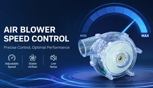
These principles prove why running a fixed-speed air blower with mechanical throttling (such as dampers or iris valves) is inefficient. Throttling introduces extreme system impedance, driving up acoustic noise while wasting energy. Conversely, using electronic air blower speed control on a TKFAN air blower scales the input electrical power down cubicly relative to speed reductions. Lowering your TKFAN air blower speed by just 20% slashes power consumption by nearly 50% while drastically dampening acoustic vibrations.
Limitations of Uncontrolled, Fixed-Speed Air Blower Systems
Engineers who implement single-speed, uncontrolled air blower units face severe engineering compromises during real-world deployments:
| Engineering Vector | Fixed-Speed Air Blower System | TKFAN Air Blower Speed Control System |
|---|---|---|
| Energy Efficiency | Operates continuously at 100% duty cycle; consumes maximum power regardless of system thermal state. | Scales power consumption exponentially down to low-power standby or idle states via PWM tuning. |
| Acoustic Performance | Generates persistent, unmitigated maximum dBA sound levels; causes user fatigue. | Modulates sound profile down to ultra-quiet operation (<20 dBA) during low-load periods. |
| Mechanical Lifespan | Continuous maximum RPM accelerates bearing wear and subjects motor drive electronics to constant thermal stress. | Reduces cumulative bearing fatigue and thermal stress, dramatically extending mean time between failures (MTBF). |
| Impedance Adaptation | Static pressure drops precipitously as dust accumulates on inlet filters, leading to thermal throttling. | Closed-loop TKFAN air blower speed control ramps RPM upward to overcome clogged filters automatically. |
Core Technical Implementations of Air Blower Speed Control
Modern brushless DC (BLDC) and high-voltage AC air blower architectures rely on standardized digital communication protocols. Implementing TKFAN air blower speed control generally involves three interconnected electrical interfaces: PWM input, FG speed output, and RD alarm output.
1. Pulse Width Modulation (PWM) Input Signal
PWM represents the industry standard for digital air blower speed control. Rather than varying the absolute DC input voltage—which introduces electrical inefficiencies and voltage drops—the system supplies constant operating voltage to the BLDC driver board while sending a high-frequency digital logic pulse train to the dedicated speed control terminal.
The operational duty cycle , expressed as a percentage of high logic state duration versus total signal period, dictates motor speed. A 100% duty cycle signals maximum rated RPM, while a 15% duty cycle drops the air blower into a quiet, low-pressure idle. TKFAN air blower speed control circuitry is engineered to maintain exceptional linear response curves between 20% and 100% PWM duty cycles, eliminating dead bands and non-linear motor stutter.
2. Frequency Generator (FG) Tachometer Signal
While PWM acts as the control output from the master MCU, the FG signal completes the intelligence loop by sending real-time speed feedback back to the host system. The FG output produces a open-collector square wave pulse train whose frequency directly mirrors the physical rotation speed of the internal rotor magnet assembly.
This closed-loop feedback mechanism allows TKFAN air blower speed control systems to continuously self-adjust. If rising filter resistance slows rotor speed down, the MCU senses the drop in FG frequency and automatically increases the PWM duty cycle to re-establish target airflow.
3. Rotation Detection (RD) Lock Alarm Signal
The RD signal acts as a hardware safety guard. Under normal operating conditions, the RD terminal outputs a continuous Logic Low state. If physical debris jams the air blower impeller or a bearing fails, the internal drive IC senses rotor stall and immediately toggles the RD line to a Logic High state. This hardware interrupt allows the system MCU to issue emergency shutdown routines, notify service personnel, or trigger auxiliary cooling loops before host components suffer catastrophic thermal damage.
Industry Applications Leveraging TKFAN Air Blower Speed Control
1. Medical Equipment: CPAP Machines and Intensive Care Ventilators
In life-support ventilators and sleep apnea CPAP therapy units, precise airflow delivery is critical. Modern medical CPAP devices demand sub-second pressure transitions matching human inhalation and exhalation cycles. During inhalation, the TKFAN air blower speed control system rapidly elevates impeller speed to maintain positive airway pressure. During exhalation, the system ramps down speed within milliseconds to reduce exhalation resistance for user comfort.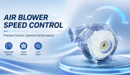
Furthermore, ultra-quiet operation is mandatory for patient sleep health. By leveraging fine-grained TKFAN air blower speed control, medical devices operate at the minimum necessary RPM during low-load states, keeping ambient acoustic noise well under 20 dBA while maintaining precise static pressure delivery.
2. Automotive ADAS Sensor Cleaning Systems
Autonomous vehicles rely on optical LiDAR, radar, and camera suites to navigate safely. Environmental rain, snow, mud, and dust quickly obscure sensor lenses, blinding the vehicle's driving algorithms. Modern automotive architectures utilize high-pressure air blower cleaning systems to blast debris off optical surfaces.
Automotive air blower speed control operates on an event-driven cycle. The air blower remains in an ultra-low power standby mode under normal conditions. When image recognition algorithms detect lens occlusion, the main control unit fires a high-duty-cycle PWM burst to the TKFAN air blower. The unit instantly accelerates to full power, producing a high-pressure jet pulse that clears lens contamination before reverting back to low-power idle.
3. Environmental Sampling and Cleanroom Air Monitoring
Laser particle counters and environmental air samplers require fixed volumetric sampling rates (e.g., exactly 28.3 liters per minute) to generate accurate data. As air is pulled through micro-porous HEPA test filters, dirt accumulates rapidly, increasing system impedance. An uncontrolled air blower would suffer reduced flow velocity, ruining test sample validity.
Deploying a TKFAN air blower equipped with closed-loop FG feedback solves this issue completely. As filter resistance rises, the host MCU senses the subtle drop in FG frequency and continuously ramps up PWM drive power, preserving exact volumetric sampling velocity across extended testing intervals.
4. Industrial Processing and High-Voltage Equipment
Heavy packaging machinery, film air-cushion sealers, soldering rework stations, and high-voltage electrical cabinets require continuous high-pressure air streams. In high-power industrial installations using 220V power distribution, deploying specialized units from the TKFAN 220V air blower series provides continuous, high-volume performance. Integrated TKFAN air blower speed control allows industrial controllers to adjust air velocity based on material thickness, ambient temperature, or system duty cycles, dramatically slashing operational energy overhead.
Hardware Design, Signal Integrity, and Implementation Best Practices
Integrating an air blower with advanced digital speed control into an embedded hardware platform requires careful attention to electrical and mechanical engineering details.
1. Signal Matching and PWM Frequency Tuning
Always consult product datasheets to determine the recommended PWM input frequency range for your specific TKFAN air blower model (typically 15 kHz to 30 kHz). Setting the PWM frequency too low within the audible spectrum (<10 kHz) causes magnetostrictive resonance, resulting in high-pitched coil noise. Setting frequency too high can cause switching losses on the internal BLDC gate drivers.
2. Open-Collector Circuit Termination
The FG tachometer and RD alarm outputs on most TKFAN air blower models feature open-collector (or open-drain) transistor topologies. To capture clean logic voltage transitions, hardware designers must connect an appropriate external pull-up resistor between the signal line and the MCU VCC supply line .
3. EMI and Electrical Noise Suppression
Because high-speed air blower motor drives rapidly switch high currents, long signal wiring harnesses can pick up electromagnetic interference (EMI). Place decoupling capacitors close to the MCU input pins, and route sensitive FG feedback lines away from high-current power switching traces on your PCB layout.
OEM Customization Capabilities for TKFAN Air Blower Systems
Standard off-the-shelf air-moving products often fall short of meeting complex physical or electrical envelope constraints. The engineering team behind TKFAN air blower solutions specializes in tailored OEM and ODM customizations to streamline integration:
- Customized Speed Control Curves: Pre-programming custom PWM-to-RPM response curves directly into internal driver flash memory.
- Tailored Harnesses & Connectors: Supplying specified wire lengths, protective sleeving, and automotive/medical-grade terminal connectors (Molex, JST, AMP).
- Ingress Protection (IP58 / IP68): Conformal coating internal driver PCBs and encapsulating motor stator assemblies for washdown or outdoor industrial exposure.
- Custom Voltage Drivers: Manufacturing high-efficiency motor controllers engineered for 5V, 12V, 24V, 48V DC, or specialized 220V AC input sources.
Frequently Asked Questions (Technical FAQ)
Conclusion
Implementing precision air blower speed control transforms conventional air blower units from static cooling components into dynamic, intelligent pneumatic systems. Integrating PWM, FG, and RD control protocols delivers significant energy savings, low acoustic footprints, precise pressure delivery, and enhanced hardware reliability across medical, automotive, and industrial devices.
Whether you require sub-miniature medical CPAP fans, high-pressure automotive sensor cleaners, or heavy-duty industrial processing units, selecting a TKFAN air blower ensures access to industry-leading thermal and pneumatic engineering. Explore our complete series and contact our technical team today to optimize your next-generation hardware designs.