

How Airflow Resistance Changes Air Blower Performance: An Engineering Guide to System Impedance & P-Q Curves
Every engineering team selecting an air blower for embedded systems eventually encounters a frustrating reality: the free-air CFM rated in product datasheets rarely matches the actual delivered airflow inside a finished enclosure. The culprit is airflow resistance—also known as system impedance.
Selecting an air blower solely based on zero-resistance parameters ignores how TKFAN airflow resistance alters real-world operational performance. Even a premium TKFAN air blower suffers significant flow drop when overcoming heavy system backpressure. This article breaks down fluid dynamic principles, P-Q performance curves, and selection methodologies to help OEM engineers prevent overheating, acoustic noise spikes, and premature hardware failure.
What Exactly Is Airflow Resistance in Blower Applications?
In fluid mechanics, airflow resistance refers to the cumulative drag and pressure drops encountered by air as it travels through a physical system. When air moves across dust filters, narrow ducts, sharp 90-degree elbows, congested PCB layouts, or specialized nozzles, friction and turbulence restrict its motion. A high-performance TKFAN air blower must generate sufficient static pressure to push or pull air past these restrictions.
The System Resistance Law:
P = K × Q²
Where P represents required static pressure, Q is the volumetric airflow, and K is the system impedance coefficient. Because pressure loss increases with the square of flow velocity, doubling the targeted air volume requires four times the static pressure output from the air blower.
In typical OEM equipment utilizing a TKFAN air blower, primary sources of system impedance include:
- Filtration Media: HEPA filters in particle counters and medical respiratory filters that continuously accumulate dust, causing TKFAN airflow resistance to increase over time.
- Restricted Ductwork: Miniature channels, abrupt cross-sectional changes, and sharp bends within compact medical or automotive enclosures.
- Enclosure Ventilation Limitations: Undersized intake/exhaust grilles and densely packed electronic components that block fluid paths.
- Application Loads: High-resistance air cushion nozzles, CPAP tubing, and automated cleaning jets on LiDAR sensors.
Dynamic vs. Static Resistance Considerations
A critical mistake in thermal engineering is treating system resistance as a static variable. As equipment operates in field conditions, dust accumulation on filters, mechanical wear, and temporary tube kinking gradually elevate overall resistance.
An optimal TKFAN air blower selection accounts not only for clean-filter baseline resistance, but also for worst-case end-of-life operating conditions.
The Core Relationship: Airflow Resistance & Blower P-Q Curves
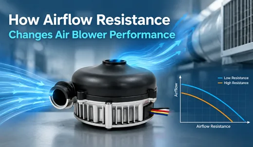
To evaluate how system impedance affects performance, engineers rely on the Pressure-Quantity (P-Q) curve. Comprehensive performance charts for all industrial models can be found in the official TKFAN air blower catalog.
Understanding the two axes of a standard P-Q chart is crucial for accurate component selection:
- X-Axis (Airflow Volume - CFM / m³/min): Represents volumetric flow rate. The maximum point corresponds to Free Air Flow—achieved only at absolute zero pressure resistance.
- Y-Axis (Static Pressure - Pa / mmH2O / InH2O): Represents static pressure capability. The peak point corresponds to Cut-Off / Shut-Off Pressure, where airflow drops to zero under total blockage.
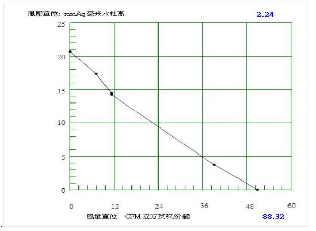
The Operating Point Intersection
The actual operational state of an air blower inside equipment is determined exclusively by the intersection of the blower's aerodynamic P-Q curve and the parabolic system resistance curve ($P = K \times Q^2$).
When system impedance increases ($K$ value grows steeper), the operating point shifts upward and to the left along the curve. Consequently, actual delivered air volume drops while the required static pressure rises dramatically.
Why Centrifugal Blowers Overcome Resistance Better Than Axial Fans
Axial fans draw and discharge air in a straight parallel path. While efficient in open-air environments with zero backpressure, their pressure-building capability is minimal. Under moderate backpressure, axial fans stall, resulting in catastrophic flow loss.
In contrast, a centrifugal TKFAN air blower draws air axially into the impeller eye and accelerates it radially outward at a 90-degree angle through a scrolled housing. This mechanical architecture converts kinetic energy into intense static pressure. Therefore, when encountering significant TKFAN airflow resistance, centrifugal blowers maintain stable, reliable airflow where axial fans fail completely.
Real-World OEM Applications & Impact of Airflow Resistance
Examining actual engineering deployment scenarios illustrates how system impedance dictates fan selection across critical OEM sectors:
1. Medical Ventilators & CPAP Units
Medical breathing devices encounter complex resistance from humidifiers, bacteria filters, flexible tubing, and dynamic patient airway pressure. Specialized medical TKFAN air blower units utilize flat, highly controllable P-Q curves to maintain stable pressure without generating excessive acoustic noise.
2. Automotive LiDAR & Sensor Cleaning
Autonomous vehicle sensors use targeted air bursts through micro-nozzles to clear rain and debris. These tiny nozzle orifices create extreme local backpressure. High-pressure DC blowers overcome this severe TKFAN airflow resistance to deliver effective cleaning force.
3. Particle Counters & Cleanroom Samplers
Air quality monitoring equipment pulls sample air through dense HEPA filters. As filters clog, resistance climbs continuous. Utilizing PWM speed control, intelligent air blower systems dynamically increase RPM to compensate for filter loading, keeping flow rates perfectly constant.
4. Air Cushion Packaging Machines
Industrial packaging machines inflate protective air pillows continuously. Inflation nozzles generate fluctuating pressure resistance. Robust brushless motor blowers handle rapidly changing impedance without overheating or losing velocity.
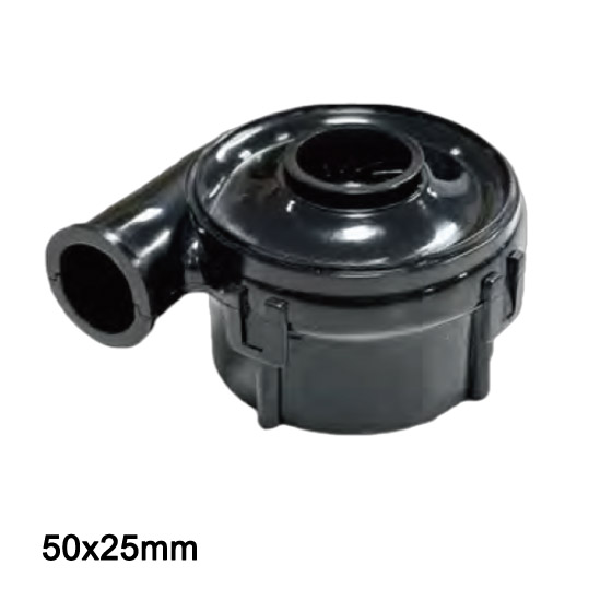
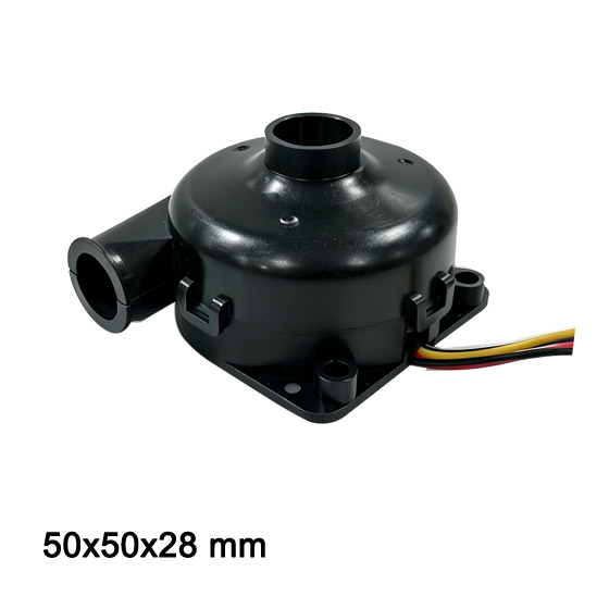
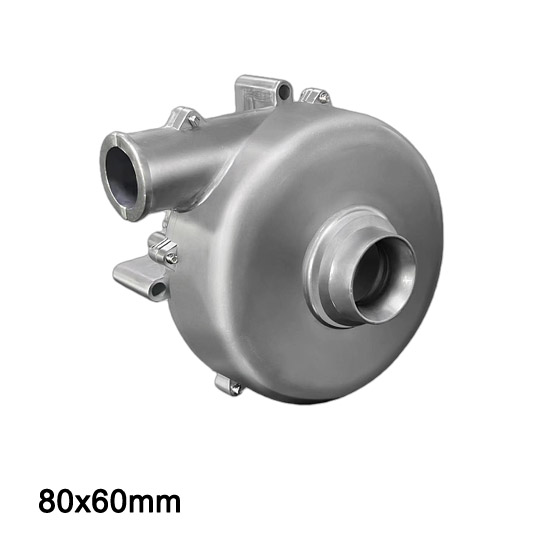
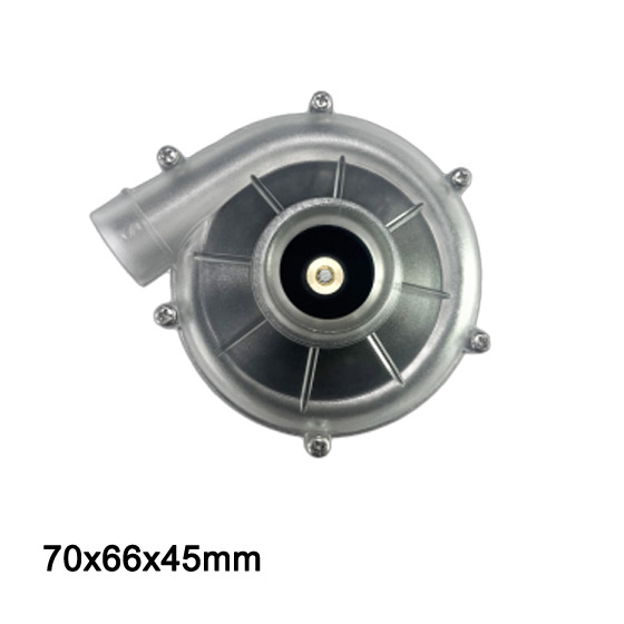
Blower product images
Explore precision-engineered blowers (click image to enlarge)
Common Engineering Mistakes When Ignoring Airflow Resistance
- Sizing Blowers via Datasheet Free-Air CFM: Free-air airflow is measured at zero backpressure. Choosing an air blower solely on this number guarantees underperformance in enclosed hardware.
- Designing Only for Clean Filters: Failing to account for dirt accumulation leads to thermal failure after weeks or months of field operation as TKFAN airflow resistance rises.
- Using Axial Fans in High-Impedance Systems: Placing axial fans behind dense dust filters or narrow conduits leads to aerodynamic stall, intense turbulence, and poor airflow.
- Underestimating Internal Enclosure Drag: Sharp internal chassis bends, wire harness blockages, and cramped PCB spacing introduce substantial secondary pressure losses.
- Overlooking Acoustic and Efficiency Shifts: Forcing a blower to operate near its shut-off point forces the motor into an inefficient zone, causing severe acoustic vibration and reduced bearing life.
Step-by-Step Practical Workflow for Blower Selection
Follow this structured engineering protocol to select the right TKFAN air blower model for high-resistance environments:
Step 1: Calculate Total System Impedance ($K$ Factor)
Sum all pressure drops across filters, ducts, grilles, and nozzles. Use CFD simulation during early prototyping and perform physical differential pressure measurements on physical chassis prototypes. Always calculate worst-case dirty filter pressure losses.
Step 2: Define Operating Point Requirements
Establish two critical metrics: targeted air volume ($Q$) and required static pressure ($P$) needed to overcome maximum anticipated TKFAN airflow resistance.
Step 3: Overlay System Curve onto TKFAN P-Q Datasheets
Plot your parabolic system curve ($P = K \times Q^2$) onto candidate P-Q curves available in the TKFAN air blower catalog. Ensure the intersection lies near the Best Efficiency Point (BEP) and well clear of the stall region.
Step 4: Implement Closed-Loop PWM & Tachometer Control
For dynamic impedance environments, select brushless blowers with PWM speed control and FG speed feedback signals to dynamically adjust motor RPM as resistance changes over the product life cycle.
Step 5: Validate via Physical Prototype Testing
Test candidate samples in full operational enclosures under actual environmental conditions. Measure actual flow, operating pressure, temperature rise, and acoustic dBA.
Frequently Asked Questions: Air Blower Performance & Resistance
Q1: What is the main difference between free-air CFM and working airflow?
Free-air CFM measures maximum airflow at zero static pressure backpressure. Working airflow is the actual volume delivered inside equipment after overcoming total system airflow resistance.
Q2: Can severe airflow resistance damage a TKFAN air blower?
Operating near total shut-off pressure creates aerodynamic stall, excessive vibration, motor overheating, and accelerated bearing wear, significantly shortening blower service life.
Q3: When should I select a centrifugal blower over an axial fan?
Choose a centrifugal air blower whenever your system features dense dust filters, long narrow ducts, small nozzles, or cramped internal components that generate notable pressure resistance.
Q4: How does PWM speed control help compensate for TKFAN airflow resistance?
PWM control allows system firmware to increase blower RPM as filters become dirty, ramping up static pressure output to maintain a consistent volumetric flow rate throughout the equipment's lifespan.
Q5: Where can I download complete P-Q performance curves for TKFAN blowers?
Full technical datasheets, 2D/3D CAD drawings, and aerodynamic P-Q charts are available on the official TKFAN air blower product page.
Q6: How does system impedance affect blower noise levels?
Operating an air blower far away from its Best Efficiency Point (BEP)—especially near stall or shut-off conditions—causes turbulence, airflow separation, and a sharp increase in acoustic dBA.
Q7: What voltage options are available for industrial TKFAN air blower models?
TKFAN manufactures compact and high-pressure blowers in 5V, 12V, 24V, and 48V DC configurations, as well as customized AC models for diverse industrial and OEM medical applications.
Q8: How do dynamic resistance changes impact medical CPAP blowers?
Patient inhalation and exhalation dynamically shift airway pressure. A medical-grade TKFAN air blower relies on low-inertia impellers and fast motor response to adjust instantly to fluctuating resistance.
Q9: Can custom housing modifications reduce internal TKFAN airflow resistance?
Yes. TKFAN provides custom OEM engineering services to optimize blower housing scroll profiles, intake bell-mouths, and outlet flanges to minimize turbulence and improve system efficiency.
Q10: What is the fastest way to request OEM blower samples for resistance testing?
Engineers can submit application specifications directly online. TKFAN offers fast-turnaround custom sample delivery in as little as 48 hours for qualification testing.
Summary
Understanding airflow resistance is essential for successful cooling and ventilation system design. Rather than relying on free-air CFM figures, engineering teams must evaluate P-Q curves against real-world system impedance. Selecting a properly rated TKFAN air blower ensures long-term reliability, quiet operation, and optimal thermal performance across demanding OEM applications.