

Centrifugal Blower vs. Axial Fan: The Ultimate Engineering Comparison Guide
In thermal management and industrial fluid dynamics, selecting the correct air-moving device is one of the most critical decisions mechanical engineers, OEM designers, and system integrators face. The choice between a centrifugal blower and an axial fan determines not only heat dissipation performance, but also acoustic emission, energy efficiency, structural footprint, and long-term device reliability.
While both devices convert electrical energy into kinetic airflow via rotating impellers or blades, their physical operating principles, fluid dynamic behaviors, and pressure generation mechanisms are fundamentally distinct. A common engineering error is treating these two technologies as interchangeable. Installing an axial fan into a high-resistance, densely packed system often leads to aerodynamic stall, excessive vibration, and thermal throttling. Conversely, specifying a centrifugal blower for open, unrestricted enclosures can result in unnecessary cost, added weight, and inefficient power draw.
This technical guide provides a deep-dive engineering analysis of Centrifugal Blowers vs. Axial Fans. We will examine working mechanics, static pressure capabilities, airflow directionality, space utilization in compact OEMs, and clear selection frameworks for industrial, medical, automotive, and electronics cooling applications.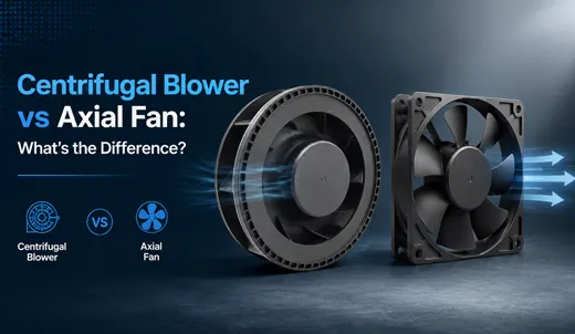
1. What is a Centrifugal Blower?
A centrifugal blower (frequently referred to as a centrifugal fan, squirrel-cage blower, or radial fan) is a dynamic air-moving system engineered primarily to generate high static pressure. The core architecture comprises a curved impeller (with forward-curved, backward-curved, or radial blades) enclosed within a specialized scroll-shaped housing, often referred to as a volute.
Working Principle of Centrifugal Blowers
The fluid dynamics of a centrifugal blower rely on the centrifugal force imparted to the air stream:
- Axial Intake: Air is drawn into the center (eye) of the rotating impeller parallel to the motor shaft.
- Radial Acceleration: As the impeller rotates, kinetic energy is transferred to the air particles, forcing them outward along the blade surfaces toward the outer diameter of the housing via centrifugal acceleration.
- 90-Degree Directional Shift: The air stream turns 90 degrees relative to its entry vector.
- Diffuser Pressure Conversion: The increasing cross-sectional area of the volute housing acts as a diffuser, converting high kinetic velocity into static pressure before discharging the air through a concentrated rectangular or square outlet.
When an impeller is operated without a volute housing, it is designated as a centrifugal impeller or motorized wheel. When paired with a precisely engineered scroll housing, it becomes a complete centrifugal blower assembly.
Key Performance Attributes of Centrifugal Blowers
- High Static Pressure Generation: Capable of operating within pressure regimes ranging from 500 Pa to over 10,000 Pa, allowing air movement through tight ductwork, dense HEPA filtration, and micro-channel heatsinks.
- Focused, Directional Air Delivery: Delivers a concentrated column of pressurized air directly to localized hot spots or targeted ducting networks.
- High Impedance Stability: Exhibits minimal flow degradation when system resistance increases due to dust buildup or air channel restriction.
- Integrated Smart Controls: Advanced models feature PWM (Pulse Width Modulation) speed control, FG (Frequency Generator) tachometer signal outputs, and RD (Rotation Detector) alarm logic for closed-loop thermal control systems.
2. What is an Axial Fan?
An axial fan represents the most widely implemented fan design globally. Named after its linear airflow vector, an axial fan moves air along the central axis of its motor shaft. The structure consists of a propeller-style multi-blade rotor housed within a cylindrical or square perimeter frame.
Working Principle of Axial Fans
Unlike centrifugal blowers, axial fans operate on aerodynamic lift principles similar to aircraft wings:
- Linear Induction: Rotating blades create a pressure differential between the front and rear surfaces of the blade profile.
- Axial Displacement: Air is drawn in linearly from the suction side and discharged parallel to the axis of rotation out the exhaust side.
- Straight-Through Velocity Flow: Air passes straight through without a 90-degree vector shift, maintaining continuous high velocity in open spaces.
Axial fans are widely produced in standardized square frame dimensions (e.g., 40mm, 60mm, 80mm, 120mm, up to 200mm+) with operational voltages including 12V, 24V, and 48V DC, as well as AC options for industrial enclosures.
Key Performance Attributes of Axial Fans
- High Free-Air Delivery (CFM): Moves large volumetric quantities of air in unrestricted or low-resistance environments.
- Symmetrical Linear Footprint: Requires straight-through clearance (front-to-back intake and exhaust) within the system enclosure.
- Cost-Effective Mass Ventilation: Simple blade and frame molding makes axial fans highly economical for general ambient air exchange.
- Static Pressure Threshold Limitations: Most standard axial fans struggle when operating against static pressures exceeding 150–500 Pa.
3. Technical Comparison: Centrifugal Blower vs. Axial Fan
To assist thermal engineers in component evaluation, the table below contrasts the fundamental physical, mechanical, and performance characteristics of centrifugal blowers and axial fans:
| Performance Parameter | Centrifugal Blower / Centrifugal Fan | Axial Cooling Fan |
|---|---|---|
| Airflow Vector | Axial suction, 90° radial volute discharge | Straight-through along motor shaft line |
| Static Pressure Range | Very High (500 Pa – 10,000+ Pa) | Low to Moderate (< 500 Pa) |
| Volumetric Airflow (CFM) | Moderate volume; highly compressed velocity | Very High in unrestricted environments |
| Resistance Resistance (Stall) | Stable; minimal flow loss under rising impedance | Prone to aerodynamic stall & turbulence under backpressure |
| Primary Mounting Footprint | Requires lateral exhaust clearance; thicker scroll profile | Flat profile; requires front/rear axial clearance |
| Acoustic Profile (Under Load) | Smooth acoustic signature under backpressure; low turbulence | Quiet in free air; high stall noise under high backpressure |
| Control Logic Options | Standard PWM, FG Tachometer, RD Alarm, Smart Thermal Tuning | Basic PWM on mid-tier; often static 2-wire on budget units |
| Environmental Protection | Easily potted for IP54, IP65, IP68 dust/waterproofing | Selective IP ratings; open blades prone to particulate buildup |
| Optimal OEM Use Case | Enclosed systems, narrow ducts, HEPA filters, targeted cooling | Open-cabinet exchange, chassis ventilation, free-air cooling |
4. Deep Dive: Airflow Dynamics & Static Pressure Behavior
Understanding the distinction between volumetric airflow rate (measured in CFM or m³/h) and static pressure (measured in Pa or inH₂O) is crucial for thermal optimization. The relationship between these parameters is plotted on a fan P-Q performance curve.
1. The Phenomenon of Aerodynamic Stall in Axial Fans
When an axial fan operates against excessive system resistance—such as a fine-mesh dust filter, a dense heat sink matrix, or tight internal cabling—the air stream cannot overcome the backpressure. The air detaches from the suction surface of the rotating blades, causing a stall condition.
During aerodynamic stall:
- Volumetric airflow decreases rapidly.
- Turbulent vortices form within the frame housing, causing acoustic noise to spike by 5 to 15 dB(A).
- Power consumption spikes, leading to elevated motor winding temperatures and accelerated bearing wear.
2. How Centrifugal Blowers Overcome System Impedance
Centrifugal blowers do not suffer from severe stall behavior in high-impedance environments. Because the fluid is physically accelerated outward by centrifugal force and compressed within the narrowing-to-widening geometry of the volute scroll, the energy transfer is mechanical rather than purely lift-dependent.
If a filter becomes clogged with dust, increasing system resistance by 100%, a premium TKFAN centrifugal blower typically experiences only a minor 10% to 15% reduction in air delivery. This stability makes centrifugal blowers essential for critical applications such as medical ventilators, particulate counters, and sealed industrial displays.
5. Thermal Management in Compact & Enclosed OEM Devices
As electronic devices become smaller, lighter, and more densely packed, thermal management engineers face strict space constraints. Products like AR/VR head-mounted displays, portable medical monitors, automotive ADAS sensors, and handheld point-of-sale terminals leave almost no room for straight-through axial airflow pathways.
Four Reasons Centrifugal Blowers Excel in Compact Devices
- Right-Angle Airflow Routing: Small electronic housings rarely feature opposing intake and exhaust grilles. A centrifugal blower can pull cool ambient air through a surface vent on top of the enclosure and blast it out laterally along the PCB surface, directly across hot processors or power MOSFETs.
- Thin-Profile Integration: Ultra-thin micro blowers (such as TKFAN’s 40mm x 40mm x 10mm series) can be mounted flat against the main circuit board, maintaining low device thickness while delivering adequate cooling.
- Micro-Duct and Air Nozzle Compatibility: When heat must be moved away from a sealed optical engine (as in AR/VR headsets or pico projectors), a centrifugal blower can force air through narrow flexible tubing or micro-molded ducts without losing velocity.
- Vibration and Acoustic Mitigation: Precision dynamic balancing of centrifugal impellers eliminates low-frequency casing resonance. Combined with acoustic damping in the volute, TKFAN blowers operate at noise levels as low as 16 to 22 dB(A), meeting stringent medical and wearable standards.
6. Step-by-Step OEM Fan Selection Protocol
To avoid costly tool re-designs or thermal failures during pilot production, engineering teams should follow this step-by-step selection framework:
Step 1: Estimate Total System Impedance
- Does the design include HEPA or foam dust filters?
- Does the airflow route through long, narrow, or elbow-bent ducts?
- Are internal components tightly packed with less than 30% free open volume?
Decision Rule: If YES to any of the above, select a Centrifugal Blower. If NO and the enclosure is wide open, select an Axial Fan.
Step 2: Determine Enclosure Geometry & Vent Positions
- If intake and exhaust vents are on opposite sides in a straight line → Axial Fan.
- If air intake is on the top/bottom face and exhaust must exit out the side or narrow edge → Centrifugal Blower.
Step 3: Define Control Signals and Operating Voltage
- 12V DC: Ideal for portable consumer devices, handheld medical monitors, and small automotive electronics.
- 24V DC: Industry standard for CPAP medical equipment, factory automation controllers, and laboratory instruments.
- 48V DC: Optimized for telecom micro-basestations, server racks, and high-power industrial power supplies.
- Control Integration: Specify PWM for variable speed tuning based on ambient temperature sensors, and FG/RD for fault detection.
Step 4: Verify Environmental Factors
If the device operates outdoors, in high-humidity medical conditions, or in dust-heavy industrial settings, ensure the blower motor is potted to meet **IP54, IP65, or IP68** ingress protection standards.