
12V DC Fan vs 24V DC Fan: Which One Should Industrial Equipment Choose?
Match the fan to the rail your machine already has. If the equipment runs on a 24 V DC industrial bus — PLC cabinets, energy-storage racks, EV-charger bays, robot cells — specify a 24V DC fan. If it runs on a 12 V battery pack or a 12 V rail — portable instruments, in-vehicle units, compact medical devices — specify a 12V DC fan. Airflow and static pressure come from the impeller and motor, not from the voltage label; what voltage actually changes is current, cable voltage drop, wiring cost and EMI.
Key takeaways
- Double the voltage, halve the current. Because P = U × I, a 9.6 W fan draws 0.8 A at 12 V but only 0.4 A at 24 V.
- Cable loss scales with current. On a 10 m, 0.75 mm² harness feeding six fans, a 12 V rail loses about 14% of its voltage; the equivalent 24 V rail loses about 3.5%.
- Same frame, same performance. A TKFAN 12V DC fan and a TKFAN 24V DC fan in the same 120×38 mm frame are built to the same PQ curve — the difference is electrical, not aerodynamic.
- 24 V is the industrial default. IEC 61131-2 defines a 24 V DC nominal control rail with a ±20% window (19.2–28.8 V) — the ecosystem PLCs, sensors and solenoids already live in.
- Safety is a tie. Both voltages sit far below the 60 V DC SELV limit, so neither option is "safer" in normal operation.
Every thermal design review eventually reaches the same fork in the road: do we cool this enclosure with a 12V DC fan or a 24V DC fan? The two families look interchangeable — often the same 40, 60, 80, 92, 120, 140 or 172 mm frame, the same four mounting holes, the same two-wire or four-wire lead — which is exactly why so many teams decide on unit price and discover the consequences eighteen months later in the field.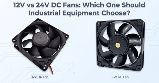
The consequences are rarely dramatic. They are mundane and expensive: a fan that spins 8% slower than specified because the supply sagged across a long harness, a cabinet that trips its overtemperature alarm on the hottest week of summer, an EMC retest that fails because a 3.6 A fan loop sits 40 mm from an encoder cable. All three trace back to a voltage decision made on a drawing that never showed the cable length.
TKFAN builds both platforms on the same production lines: the TKFAN 12V DC fan series and the TKFAN 24V DC fan series. Both cover 40–172 mm industrial frames with PWM speed control, FG tach output, IP54/IP65 protection options and wide-temperature BLDC motors. This guide is the selection logic our own application engineers use when a customer sends in a cabinet drawing — the formulas are shown so you can reproduce every number against your own harness.
1. One equation explains the entire debate: P = U × I
Power equals voltage multiplied by current. Fan makers hold power roughly constant when they build the same impeller and stator in two voltage variants, so doubling the supply voltage halves the current. A 9.6 W axial fan therefore draws 0.8 A on 12 V and 0.4 A on 24 V.
That single division cascades into everything engineers argue about afterwards: conductor gauge, connector current rating, heat inside the terminal block, the magnetic field the supply loop radiates into a nearby signal cable, and how much voltage survives a ten-metre run inside a 2 m cabinet.
Put another way, a 12V DC fan and a 24V DC fan of equal wattage are aerodynamic twins and electrical opposites. Every downstream decision — connector rating, wire gauge, fuse size, filter placement — follows from the current, not from the airflow column of the datasheet.
The second relationship is the one datasheets tend to bury — the fan laws. For a given fan geometry, airflow scales linearly with speed, static pressure with the square of speed, and shaft power with the cube. A 10% speed loss, precisely what a starved BLDC motor produces, costs about 19% of static pressure and 27% of power. Static pressure is the force that pushes air through a loaded filter mat or a dense fin stack, so a modest voltage sag shows up as a disproportionate thermal problem. The reference procedure behind any credible PQ curve is ANSI/AMCA 210-25, Laboratory Methods for Testing Fans for Aerodynamic Performance Rating, published by the Air Movement and Control Association.
Why this matters at the enclosure level: a fan rated 100 CFM at 0 Pa may deliver only 60 CFM at 40 Pa of system impedance. If you also lose 10% of speed to voltage drop, delivered airflow falls toward 54 CFM — and the cabinet that passed thermal validation on the bench now runs 15 °C hotter in the field.
2. 12V DC fan vs 24V DC fan: six dimensions that decide the design
The table below is the comparison our engineers run through in a design review, pitting a typical 12V DC fan against a 24V DC fan of the same frame. Test conditions for the TKFAN figures: 25 °C ambient, standard atmospheric pressure, unrestricted intake.
| Dimension | 12V DC fan | 24V DC fan | Engineering consequence |
|---|---|---|---|
| Current at equal power | Higher (2×) | Halved | Long harnesses and multi-fan banks favour 24 V |
| Voltage drop, same cable | 2× the drop | Half the drop | Runs over 3 m or 3+ fans in parallel: choose 24V DC fan |
| Cable and connector cost | Needs a larger gauge | Standard gauge is enough | Copper is sold by mass; savings grow with fan count |
| Electrical safety class | SELV (<60 V DC) | SELV (<60 V DC) | Both satisfy IEC 61131-2; no practical shock hazard |
| EMI behaviour | Higher loop current, stronger field | Lower loop current | Sensor-dense and bus-heavy cabinets favour 24 V |
| Native supply availability | Batteries, portable and consumer gear | PLC, PAC, robot, sensor and ESS standard | Never add a converter you do not need |
Table 1 — Voltage is an electrical decision with thermal consequences. Airflow and pressure are set by the impeller, stator and blade geometry, which are identical across the two TKFAN voltage variants of the same frame.
3. The voltage-drop arithmetic that decides long-cable projects
DC cable loss is calculated with a two-term formula, because current must travel out and back:
V_drop = 2 × L × I × RHere L is the one-way cable length in metres, I the working current in amperes, and R the conductor resistance per metre. For annealed copper at 20 °C, R = 0.0175 / A Ω per metre with the cross-section A in mm². A common 0.75 mm² industrial lead therefore has R ≈ 0.0233 Ω/m, and a 0.5 mm² lead R ≈ 0.035 Ω/m. That is why a 12V DC fan tolerates far less cable than a 24V DC fan of the same power, and why the difference only becomes visible once fan count and cable length grow.
Now apply it to a realistic cabinet: six 120 mm fans, each drawing 0.6 A at 12 V (7.2 W), wired on a single 0.75 mm² harness. On 24 V the same fans draw 0.3 A each.
| Harness scenario (0.75 mm² Cu) | 12V DC fan | Terminal voltage | 24V DC fan | Terminal voltage |
|---|---|---|---|---|
| 1 fan, 0.6 A, 2 m run | 0.06 V (0.5%) | 11.94 V | 0.03 V (0.1%) | 23.97 V |
| 6 fans, 3.6 A, 5 m run | 0.84 V (7.0%) | 11.16 V | 0.42 V (1.8%) | 23.58 V |
| 6 fans, 3.6 A, 10 m run | 1.68 V (14.0%) | 10.32 V | 0.84 V (3.5%) | 23.16 V |
Table 2 — Calculated with V_drop = 2 × L × I × R, copper at 20 °C. Note how the 12 V rail exits the ±10% band that most fan datasheets require for full rated performance, while the 24 V rail stays comfortably inside it.
The usual reflex is to thicken the cable. Copper is priced by mass, so pulling the 12 V case back from 14% loss to 3.5% means roughly quadrupling the conductor cross-section — 0.75 mm² to about 3 mm² — which is neither cheaper nor easier to route inside a 600 mm-wide cabinet with a wire duct already at capacity. When a project must stay on 12 V, TKFAN engineers recommend one of three fixes instead: move the power supply closer to the fan wall, split the bank into separately fused groups of two or three fans, or accept a lower-speed fan model and size the thermal design around the reduced airflow.
4. Start with the native supply rail, not with the fan
In most projects this single question resolves the debate before any performance comparison begins: what does the machine already output?
24 V native systems
Programmable controllers, PACs, industrial robots, proximity switches, photoelectric sensors, solenoid valves and motor-drive logic are all built around a 24 V DC rail. IEC 61131-2:2017 — the equipment requirement and test standard for programmable controllers — specifies a 24 V DC nominal supply with a permitted window of 19.2 V to 28.8 V, i.e. ±20%. If your cabinet already distributes 24 V, a TKFAN 24V DC fan connects directly: no buck converter, no extra heat source, no additional failure point, no new EMC problem to solve.
12 V native systems
Portable instruments, in-vehicle equipment, 3S lithium packs (9.0–12.6 V), 12 V lead-acid systems (10.5–13.8 V) and many small medical and 3D-printing devices run on 12 V. Here a TKFAN 12V DC fan is the natural choice, and adding a boost converter to reach 24 V buys nothing but cost and noise.
The converter penalty
Every conversion stage costs something. Industrial DC-DC modules typically run at 88–93% efficiency (Infineon DC-DC converter portfolio and efficiency benchmarks), which means 7–12% of the fan's power is dissipated as heat inside the very enclosure you are trying to cool, plus a component that can fail, plus switching noise that must be filtered. Matching the native rail is almost always the cheapest engineering decision available.
5. Safety, ingress protection and the thermal envelope
Both voltages are classed as safety extra-low voltage. At 12 V and 24 V, both sit far below the 60 V DC SELV ceiling referenced by IEC 61131-2 and by enclosure protection practice under IEC 60529 (the IP code). Neither presents a shock hazard in normal service, so "12 V is safer" is not a valid selection argument in industrial equipment — the difference is current, not touch voltage.
What does differ is the hardware around the fan. The TKFAN 12V DC fan and the TKFAN 24V DC fan are both available to IP54 and IP65 when ordered with conformal-coated PCBs and sealed motor caps, rated for −20 °C to +70 °C operation, with UL 94 V-0 flame-retardant PBT housings and impellers. That protection, however, is voltage-specific: the drive IC, the coil insulation class and the internal clamp network are designed around one nominal input. Never re-pin a 12 V fan onto a 24 V rail. Doubling the input does not make the fan spin faster; it destroys the commutation circuit, usually within seconds, and it voids the warranty.
6. Bearing life, L10 ratings and the 10 °C rule
Bearing life is where selection mistakes become warranty claims. ISO 281:2007 defines the basic rating life L10 as the life that 90% of a bearing population reaches under a given load — in plain terms, the point at which one fan in ten has failed.
TKFAN dual-ball-bearing fans, in both the 12V DC fan and 24V DC fan ranges, are rated at 70,000 hours L10 at 25 °C and 50,000 hours at 40 °C. Sleeve-bearing versions land around 30,000 hours at 25 °C. Fifty thousand hours at 40 °C is 5.7 years of uninterrupted 24/7 duty — the difference between a fan that survives a warranty period and one that defines it.
Voltage does not change bearing life directly; voltage stability does. A fan held at 88% of nominal runs at lower speed but at higher current for the same load, and the drive IC runs hotter. The Arrhenius relationship — often stated as the 10 °C rule — says that every 10 °C of additional operating temperature roughly halves the life of grease and of electrolytic components. A 12 V fan starved on a long harness therefore ages faster not because of the voltage label, but because of the extra heat its electronics generate while struggling to hold speed.
The practical conclusion: neither a 12V DC fan nor a 24V DC fan is intrinsically longer-lived. What shortens life is a rail that cannot hold its nominal value under load — a harness design problem, not a voltage problem.
7. EMC, PWM control and acoustic behaviour
Modern cabinets are full of weak signals: encoder lines, 4–20 mA loops, RS-485 and CAN buses. Magnetic field strength around a conductor is proportional to current, so a 3.6 A fan loop on 12 V radiates roughly twice the field of the 1.8 A loop that delivers identical power at 24 V, and a higher dI/dt at commutation couples more readily into parallel signal wires. In cabinets that must pass EN 61000-6-2 immunity and EN 61000-6-4 emission, the lower-current rail is simply easier to certify.
Control behaviour is identical whether you specify a 12V DC fan or a 24V DC fan. TKFAN fans accept a standard 0–5 V (or open-collector) PWM signal at 20–25 kHz with duty from 20% to 100%, and provide an FG tachometer output of two pulses per revolution so a PLC can verify actual speed rather than assume it. Where the two differ is in the harness: a long PWM lead running beside a high-current 12 V feed needs shielding that the same lead beside a 24 V feed does not. Acoustically, both variants of a given frame produce the same sound power at the same speed — the noise difference people "hear" between voltages is almost always a speed difference caused by supply droop.
8. Total cost of ownership: the fan is the cheap part
Unit price rarely decides this. The table below compares a 24 V-native cabinet with six 120 mm fans against the same cabinet forced onto 12 V fans. Figures are indicative, USD, 2026 production volumes.
| Cost line | 6 × TKFAN 24V DC fan (native) | 6 × TKFAN 12V DC fan on a 24 V machine |
|---|---|---|
| Fans | $54 | $54 |
| DC-DC converter (24→12 V, 10 A) | — | $18 |
| Harness (long run, voltage drop corrected) | $6 (22 AWG) | $11 (16 AWG) |
| EMI mitigation (ferrites, shielded PWM lead) | — | $6 |
| Extra assembly and test time | — | $6 |
| Indicative total | ≈ $60 | ≈ $95 |
| Added failure points | 0 | 1 converter, 2 connectors, 1 fuse |
Table 3 — The fan price is identical; the system cost is not. Converter losses also add heat inside the enclosure, which the cooling system must then remove.
9. Application selector: what we recommend, and why
| Application | Recommended | Reason |
|---|---|---|
| PLC / automation control cabinet | 24V DC fan | Native 24 V DIN rail supply, low EMI, no converter |
| Battery energy storage (ESS) rack | 24V DC fan | Many fans, long runs, low current keeps drop under control |
| EV charger power bay | 24V DC fan | Controller and metering electronics already on 24 V |
| Robot cell / machine tool | 24V DC fan | Sensor-dense environment, EMC margin matters |
| Telecom and network enclosure | 24V DC fan (or 48 V variant) | Bus-fed equipment, central 24/48 V distribution |
| Portable medical instrument | 12V DC fan | Battery-powered, low acoustic requirement, short leads |
| In-vehicle / telematics unit | 12V DC fan | Vehicle 12 V rail, wide input tolerance |
| Small bench instrument, single fan | 12V DC fan | Short cable, negligible drop, lowest BOM |
Table 4 — In ESS and telecom cabinets, fan count and harness length dominate; in portable devices, the battery chemistry dominates.
10. Five questions that settle the selection in a design review
- What voltage does the machine already distribute? 24 V bus → TKFAN 24V DC fan. 12 V rail or battery → TKFAN 12V DC fan.
- How long is the fan harness, and how many fans share it? Over 3 m, or three or more fans in parallel, favours 24 V; a single fan on a 500 mm lead is voltage-agnostic.
- Is the enclosure sensor-dense? Encoders, analogue loops and fieldbus wiring all benefit from the lower loop current of a 24 V fan.
- Is the unit portable or mains-fed? Battery-powered units take the 12 V fan; fixed cabinets take the 24 V fan.
- What is the thermal margin? Below 20% headroom, choose the rail with the smaller voltage drop and derate the fan curve, not the datasheet headline.
11. Three myths worth retiring
Myth 1: "A 24 V fan moves more air." Airflow and static pressure come from impeller geometry, blade angle and stator design. A TKFAN 12V DC fan and a TKFAN 24V DC fan in the same frame are tested to the same aerodynamic curve under ANSI/AMCA 210-25; the difference is electrical.
Myth 2: "12 V is safe, 24 V is not." A 12V DC fan and a 24V DC fan are both SELV, and both are covered by the same IEC 61131-2 requirements for industrial control equipment. The safety argument is a tie, and using it to justify a decision usually hides a supply-rail problem.
Myth 3: "Just drop in a DC-DC module and the choice doesn't matter." Each conversion adds loss, heat, a failure point and an EMC task. It is a legitimate fix when a platform must be reused across voltages — it is not a neutral one.
12. How TKFAN validates a fan before it ships
Claims are only as good as the test behind them, so here is the process every TKFAN 12V DC fan and TKFAN 24V DC fan goes through before it leaves the line. Every impeller rotor is dynamically balanced on two planes to reduce off-axis bearing load; every motor is run in and its current signature checked; airflow and static pressure are measured on an AMCA-style chamber against the published PQ curve; and samples from each lot run a thermal soak at 70 °C plus a 1,000-hour continuous life bench. Finished fans carry CE and UKCA marking and comply with RoHS and REACH. That is what makes a 70,000-hour L10 number a specification rather than a hope.
TKFAN 12V DC fan series — 40 to 172 mm frames
PWM and FG options, IP54/IP65 protection, dual-ball bearings, −20 °C to +70 °C
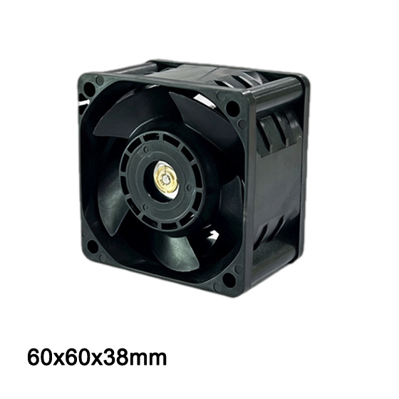 DA6038VH12B-B 60×60×38 mm · 21,700 rpm · 66.8 CFM · 1.4 kPa
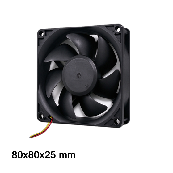 DA8025HV12B-A 80×80×25 mm · 5,000 rpm · 59.7 CFM · 0.09 kPa
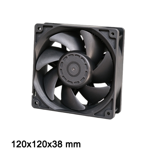 DCH12038H12B-0201 120×120×38 mm · 3,600 rpm · 123.9 CFM · 0.1 kPa
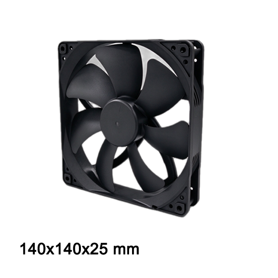 DA14025M12B-B 140×140×25 mm · 2,000 rpm · 101.2 CFM · IP-rated
TKFAN 24V DC fan series — the industrial 24 V default
Same frames and airflow as the 12 V range, half the current, built for PLC and ESS cabinets
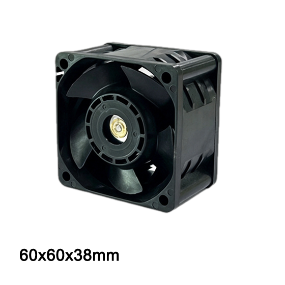 DA6038VH24B-B 60×60×38 mm · high static pressure · PWM ready
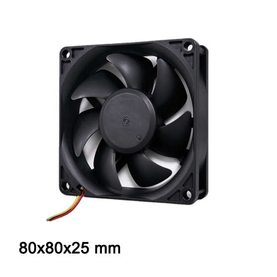 DA8025HV24B-A 80×80×25 mm · low current draw · FG tach
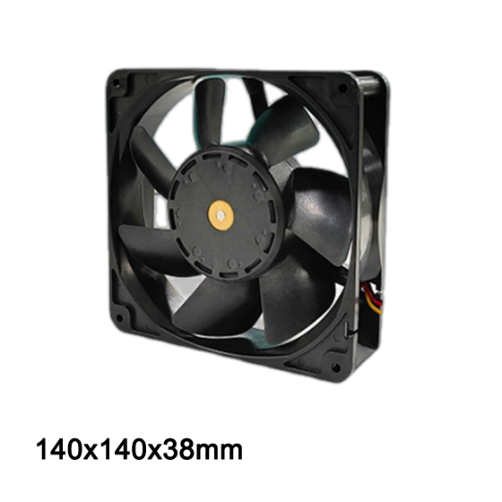 DA14038HV24X-D 140×140×38 mm · high airflow · wide temperature
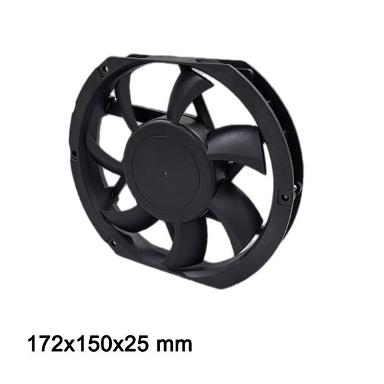 DA17225VH24B-A 172×150×25 mm · 246 CFM · drop-in replacement
13. Bottom line
There is no universally better voltage, only a better fit. Choosing a 12V DC fan for a 24 V machine, or a 24V DC fan for a 12 V platform, is the one decision that reliably costs money in every phase — BOM, assembly, certification and field service. Decide in this order: native supply rail first, harness length and fan count second, EMI environment third, thermal margin last. On a 24 V machine, a 24V DC fan removes a converter, a heat source and a failure mode. On a 12 V platform, a 12V DC fan does the same. The airflow you specified is available at either voltage — provided the voltage actually arrives at the fan.
Both ranges are stocked for samples with short lead times and can be customised with cable length, connector type (JST, Molex, Amphenol), IP protection, conformal coating and low-noise impeller trims. Browse the full specifications here: TKFAN 12V DC fan catalogue and TKFAN 24V DC fan catalogue.
14. Technical FAQ: 10 questions engineers actually ask
Q1. Which is better for industrial equipment — a 12V DC fan or a 24V DC fan?
Neither is universally better. If the machine distributes a 24 V DC bus (PLC cabinets, ESS racks, robot cells), the 24V DC fan is the correct choice because it needs no converter and produces lower cable loss and EMI. If the machine runs from a 12 V battery or rail, the 12V DC fan is correct. Airflow for a given frame is identical; only the electrical behaviour differs.
Q2. Can I run a 12V DC fan on a 24 V supply?
No. The commutation IC, coil insulation and internal clamp network are rated for the nominal input. Connecting a 12 V fan to 24 V usually destroys the drive circuit within seconds and voids the warranty. TKFAN's 12 V and 24 V ranges are separate designs, not the same board with a different label.
Q3. Do 12V and 24V DC fans move the same amount of air?
Yes, when they share the same frame, impeller and motor design. A TKFAN 12V DC fan and TKFAN 24V DC fan of the same model number move the same CFM at the same rotational speed, because aerodynamic output is a function of impeller geometry and speed, verified to ANSI/AMCA 210-25 test methods — not of the supply voltage.
Q4. How long can a 12V DC fan cable run before performance drops?
Using V_drop = 2 × L × I × R with 0.75 mm² copper, a single 0.6 A fan stays within 1% loss up to roughly 4 m. A six-fan bank of 3.6 A exceeds the ±10% window at around 7 m. As a working rule, keep 12 V fan runs under 3 m or split the bank into separately fused groups.
Q5. Why do PLC cabinets almost always use 24V DC fans?
Because IEC 61131-2 defines a 24 V DC nominal control rail (19.2–28.8 V), and every PLC, sensor, relay and solenoid in the cabinet already runs on it. Adding a 12 V fan introduces a converter, extra heat and another failure point into a system designed to run for a decade.
Q6. What is the best fan voltage for battery energy storage cabinets?
24 V in most designs. ESS racks typically carry six to twelve fans on long internal harnesses; at 12 V the parallel current makes voltage drop and copper weight significant, while the 24 V rail keeps losses near 3–4% and halves the current per conductor.
Q7. Do both voltages support PWM speed control and tach feedback?
Yes. TKFAN 12V DC fans and 24V DC fans both accept a 20–25 kHz PWM signal with 20–100% duty (0–5 V or open-collector) and output an FG signal of two pulses per revolution. Control logic is identical; only the supply loop differs, which matters for shielding on long harnesses.
Q8. Is a 24V DC fan louder than a 12V DC fan?
No. Acoustic output follows speed and blade geometry, not voltage. A 24 V fan at 2,000 rpm and a 12 V fan at 2,000 rpm in the same frame produce the same sound power. Fans "sound louder" at one voltage when a supply droop changes their actual operating speed.
Q9. Which voltage gives longer fan life?
Life is set by bearing quality, operating temperature and voltage stability, not by the nominal voltage. Both ranges reach 70,000 h L10 at 25 °C on dual-ball bearings (50,000 h at 40 °C). A chronically undervolted 12 V fan ages faster because its drive electronics run hotter while trying to hold speed.
Q10. Can TKFAN supply both voltages in the same frame, and customise them?
Yes. The 12V DC fan and 24V DC fan ranges share mounting footprints from 40 mm to 172 mm, so a single mechanical design can serve both supply architectures. Cable length, connector type, IP54/IP65 protection, conformal coating, low-noise impeller trims and wide-temperature motors are all available as options on both.
Send us your voltage, frame size, airflow target and connector type — our engineers reply with a matched model and a sample plan.