

Technical Principles of High-Airflow High-Speed High-Pressure DC Blowers
In modern industrial thermal management, medical devices, and advanced process engineering, thermal management requirements have evolved dramatically beyond basic air circulation. Modern electronics, highly dense medical equipment, and industrial processing systems operate within exceedingly tight enclosures. These compact designs generate significant fluidic impedance—often referred to as system backpressure. When engineers attempt to force air through dense HEPA filters, micro-channel heat exchangers, or convoluted ductwork, traditional cooling mechanisms fail to perform. This comprehensive guide provides an in-depth technical analysis of high-airflow, high-speed, high-pressure DC blowers, explaining how these specialized turbomachinery components generate extreme static pressure and why they are vital to contemporary high-impedance thermal architectures.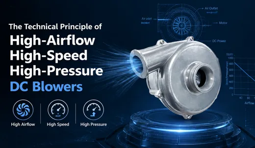
1. Defining the High-Pressure DC Blower Architecture
A high-pressure DC blower is a specialized, compact centrifugal air-moving device powered by a high-efficiency Brushless Direct Current (BLDC) motor. Unlike standard axial fans designed to move large volumes of air in open, unrestricted environments, a high-pressure DC blower is specifically engineered to generate substantial static pressure (up to 24 kPa) under high system impedance conditions. While standard axial cooling fans stall when confronted with restrictive fluid paths, high-pressure centrifugal blowers leverage internal dynamic pressure conversion to sustain optimal volumetric airflow rates.
The term "air blower" encompasses a wide array of air-moving equipment. However, in professional engineering contexts, high-speed DC blowers represent a dedicated category optimized for static pressure capability rather than free-air maximum volumetric flow. Modern miniaturized DC blowers achieve operational speeds ranging from 28,000 RPM up to 55,000 RPM. Available in frame sizes from micro-scale 50mm housings up to 200mm industrial-grade units, these components bridge the performance gap between low-pressure axial fans and large-scale, energy-intensive positive displacement air compressors.
2. Core Physics and Four-Stage Aerodynamic Cycle
The functional execution of a high-airflow, high-speed, high-pressure DC blower relies on the unified principles of centrifugal force, Bernoulli's equation of fluid dynamics, and electromagnetic energy conversion. The complete fluid dynamic cycle converts electrical energy into kinetic rotational energy, which is subsequently transformed into potential pressure energy through four continuous physical stages:
Stage 1: Axial Air Intake and Vacuum Generation
As the BLDC motor drives the impeller at high angular velocity, air within the center of the impeller (the "eye") is accelerated outward. This displacement creates a localized low-pressure zone (vacuum) at the inlet. Ambient air is drawn continuously along the axial direction (parallel to the drive shaft) into the center of the rotating impeller structure.
Stage 2: Radial Acceleration via Centrifugal Force
Once the air molecules enter the impeller channels, they encounter blades spinning at speeds between 28,000 and 55,000 RPM. Centrifugal force forces the air molecules outward along the blade surfaces, imparting tremendous kinetic energy. The air is discharged radially—perpendicular to the intake direction—executing a precise 90-degree vector shift that fundamentally distinguishes centrifugal air blowers from axial airflow configurations.
Stage 3: Dynamic Pressure Conversion within the Volute Housing
Upon leaving the outer tip of the impeller, the air enters the expanding scroll cavity, known as the volute. The geometry of the volute features a progressively increasing cross-sectional area. According to Bernoulli’s principle , as the fluid's flow area expands, its velocity decreases. This controlled deceleration converts the high kinetic energy of the moving air into static potential pressure energy—the decisive mechanism enabling the blower to overcome substantial downstream system resistance.
Stage 4: High-Pressure Discharge
The pressurized air stream is consolidated and expelled through the single, tangential discharge nozzle of the blower housing. The output is a highly focused, high-velocity stream of pressurized air capable of penetrating micro-channel heat sinks, long flexible tubing, or fine particulate filter matrices without fluidic backflow or aerodynamic stall.
It is vital to note that increasing rotational speed alone does not guarantee elevated static pressure. Optimal pressure generation relies on a precise balance between blade profile geometry, volute scroll contours, internal sealing tolerances, and dynamic balance calibration. Inferior fluid-dynamic design induces boundary layer separation and internal turbulence, leading to severe pressure losses regardless of motor RPM.
3. Anatomy of Critical High-Precision Components
Sustaining 50,000 RPM operation while maintaining long service life requires rigorous engineering across all internal components. A failure or precision shortfall in any single part compromises pressure generation, increases acoustic noise, and dramatically accelerates wear.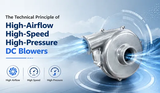
3.1 Precision Centrifugal Impeller
The impeller represents the primary aerodynamic engine of the blower. Most high-pressure DC blowers utilize forward-curved multiblade impellers. Under equivalent rotational speeds, forward-curved blades yield higher static pressure gains per unit diameter than backward-curved alternatives, making them ideal for space-constrained equipment designs. Modern impellers undergo dynamic balancing on automated dual-plane balancing machines. Unbalanced impellers operating at ultra-high speeds generate severe harmonic vibrations, leading to rapid bearing degradation and shortened service life.
3.2 Spiral Volute Housing
The volute housing governs energy conversion efficiency. Its expanding spiral contour must be mathematically optimized to minimize internal fluid friction and turbulent eddies. Sealing along housing joints is paramount; even microscopic air leaks degrade static discharge pressure. Depending on operational requirements, housings are precision-molded from UL94 V-0 flame-retardant thermoplastics (PBT/PPS) or die-cast aluminum alloys for aggressive thermal environments.
3.3 Three-Phase Brushless DC (BLDC) Motor
Brushed DC motors are unsuited for high-reliability, high-speed blower designs due to rapid brush wear and electrical arc noise. Three-phase BLDC motors deliver the requisite torque-to-weight ratio, power density, and continuous duty capability. These motors feature dual precision ball bearings with high-temperature synthetic grease, enabling reliable operation across ambient temperature ranges from -20°C to +70°C.
3.4 Integrated Drive Controller & Interface
Industrial DC blowers typically utilize a 4-wire electrical interface comprising VCC (Power), GND (Ground), PWM (Pulse Width Modulation Input), and FG (Frequency Generator/Tachometer Output). The FG signal communicates real-time rotational velocity back to the system controller, enabling active closed-loop speed regulation to maintain consistent airflow as system impedance shifts over time.
3.5 Ingress Protection and Environmental Sealing
For demanding industrial and medical environments, blower electronics undergo conformal coating or full potted encapsulation. Achieving IP55, IP67, or IP68 ingress protection safeguards motor windings and driver circuitry against moisture, conductive dust, and corrosive vapors, enabling reliable performance in harsh field conditions.
4. Parametric Comparison: Axial Fans vs. High-Pressure DC Blowers
Understanding the operational trade-offs between axial airflow designs and centrifugal high-pressure blowers is essential for selecting the correct component during initial system architecture design.
| Performance Parameter | Standard Axial Cooling Fan | High-Pressure DC Blower |
|---|---|---|
| Fluid Flow Path | Parallel to rotational axis (Linear) | Axial intake, 90° radial discharge |
| Static Pressure Range | Low (< 0.5 – 1.0 kPa) | Extreme High (2.9 kPa – 24.0 kPa) |
| Backpressure Tolerance | Poor (Stalls easily under restriction) | Exceptional (Sustains airflow through high impedance) |
| Ideal Application Zone | Open-chassis cooling, low-impedance venting | HEPA filters, dense ducts, narrow heat sinks |
| Free-Air Volumetric Flow | Very High for size | Moderate to High |
| Acoustic Profile | Quiet in open air; noisy when stalled | Consistent, predictable acoustic footprint |
| Physical Form Factor | Thin axial profile, shallow depth | Volute housing structure, deeper profile |
5. Interpreting the P-Q (Pressure vs. Flow Rate) Performance Curve
To ensure long-term system reliability, engineers must calculate total system impedance by summing pressure drops across all internal elements—such as filters, elbows, surface friction, and heat exchangers—at the target airflow rate. The operational working point is established where the system impedance curve intersects the blower's P-Q curve. Selecting a blower that only matches the nominal system impedance leaves no margin for filter loading or thermal variation, potentially causing aerodynamic stall, increased noise, and motor thermal stress.
6. Electronic Control, PWM Modulation, and Closed-Loop Logic
Modern DC blowers rely on electronic commutation control for precise thermal management. Closed-loop control systems dynamically adjust blower performance based on real-time thermal demand:
- PWM Velocity Control: The system host issues a high-frequency PWM signal (typically 15kHz to 25kHz) to the blower control driver. Adjusting the duty cycle alters the effective voltage applied to the motor stator, driving smooth, linear speed adjustments between minimum idle and maximum rated RPM.
- FG Tachometer Feedback: The FG signal outputs a square wave pulse train proportional to motor speed. System microcontrollers read this signal to verify rotational velocity, detect mechanical lock conditions, and implement closed-loop control algorithms.
- Closed-Loop Pressure Compensation: As particulate filters accumulate debris over time, system backpressure increases. System algorithms read the decreased flow or altered motor current via FG feedback and increase the PWM duty cycle, speeding up the motor to maintain the required delivery pressure and volumetric airflow.
7. Key Engineering Challenges Solved by High-Pressure Blowers
High-pressure DC blowers resolve critical fluid dynamic bottlenecks across compact, high-density hardware platforms:
- Overcoming Severe System Impedance: Compact enclosures with dense HEPA filtration or micro-channel cold plates require static pressure capability beyond the limits of axial fans. High-pressure blowers deliver up to 24 kPa of static head to maintain consistent flow rates.
- Fitting Ultra-Compact Enclosures: Delivering high static pressure from micro-frame sizes (e.g., 50mm x 25mm) enables continuous forced-air cooling in space-constrained portable devices.
- Enabling Rapid Dynamic Response: Medical ventilators and automated industrial process lines require millisecond-level pressure acceleration. Low-inertia BLDC motors and optimized impellers allow high-speed blowers to ramp from idle to maximum pressure rapidly.
- Ensuring Continuous Operational Lifespans: Utilizing precision dual ball bearings, dynamic rotor balancing, and advanced thermal management, industrial DC blowers achieve over 50,000 hours of continuous continuous operation lifetime at 40°C).
8. Critical Industrial and Medical Application Scenarios
The high-pressure capability and compact design of DC centrifugal blowers make them essential across advanced technological sectors:
- Medical Respiratory Equipment: Used in CPAP systems, High-Flow Nasal Cannula (HFNC) units, and portable ventilators. Blowers deliver rapid, precise pressure shifts while maintaining ultra-low acoustic levels for patient comfort.
- Hydrogen Fuel Cell Systems: Delivers controlled stoichiometric air supply into fuel cell stacks, overcoming internal membrane layer resistance to maintain steady power generation under dynamic electrical loads.
- Additive Manufacturing & Laser Systems: In 3D printers, blowers deliver directed, high-velocity air streams to rapidly solidify extruded polymers. In laser cutting tools, blowers remove fumes and debris to protect sensitive optical lenses.
- Automotive Autonomous Sensor Cleaning: High-pressure blowers supply rapid, focused bursts of air to clear dust, rain, and mud from LiDAR and optical camera lenses on autonomous vehicles.
- Environmental Sampling & Industrial Automation: Drives air sampling pumps, pneumatic vacuum pick-and-place mechanisms, and air knife drying systems that depend on stable positive or negative differential pressure.
9. Engineering Selection Checklist
When selecting a high-pressure DC blower, system designers should evaluate the following key parameters:
- Physical Dimensions: Verify outer frame footprint, intake diameter, and discharge nozzle dimensions match housing constraints.
- Nominal Voltage: Match operating voltage (12V DC, 24V DC, 48V DC) with available power supply rails.
- Max Static Pressure & Max Airflow: Ensure the unit's P-Q curve exceeds calculated system resistance at the design operating point.
- Drive Architecture: Choose between integrated internal drivers for simple implementation or external drivers for customized control logic.
- Monitoring Options: Confirm availability of 4-wire configurations (PWM input, FG speed output).
- Environmental Rating: Specify IP55 to IP68 water/dust ingress protection levels where environmental exposure is expected.
- Compliance Standards: Ensure components meet UL94 V-0 flame resistance, CE, RoHS, and REACH requirements.