

High-Speed DC Fan Engineering Guide: Maximizing Airflow Under High Backpressure Conditions
A Comprehensive Thermal Design Standard for High-Density Servers, Telecom Power Units, Medical Equipment, and Industrial Electronics
1. Introduction: The Thermal Challenge in Next-Gen Electronics Packaging
Modern electronic hardware engineering is continuously pushing the boundaries of power density and compact thermal architecture. High-performance blade servers, 1U/2U rackmount enclosures, telecom 5G remote radio units (RRUs), high-density switch power supplies, advanced medical imaging systems, and AI computing acceleration nodes are packing massive wattage into increasingly constrained physical spaces. As silicon power dissipation climbs, thermal engineers face a critical and costly roadblock: standard cooling fans that look exceptional on paper perform drastically below expectations inside real-world equipment.
This gap between rated performance and real-world execution is driven by system impedance, commonly referred to as backpressure or system static pressure. When air meets internal restrictions—such as micro-channel heat sinks, high-efficiency particulate air (HEPA) filters, dense cable harnesses, and crowded Printed Circuit Board (PCB) layouts—the usable airflow plummets. This loss of airflow causes localized hot spots, triggers thermal throttling of processors, accelerates component degradation, and risks catastrophic field failures.
Selecting a thermal solution based solely on free-air cubic feet per minute (CFM) rating is one of the most common pitfalls in electronic thermal management. A fan delivering high CFM in an open-air laboratory environment often fails completely when forced to push air through dense physical obstacles. This is where specialized high-speed DC fans become vital. A high-performance DC fan designed for high backpressure environments relies on optimized aerodynamics, high-torque brushless DC motors, and robust static pressure profiles to sustain effective cooling airflow where standard fans stall.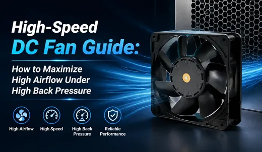
2. Fundamentals of Backpressure, Static Pressure, and System Impedance
To engineer an optimized forced-air cooling setup, thermal designers must understand the physical forces acting on the fan inside an enclosure.
Defining System Backpressure
System backpressure is the total resistive force created by an enclosure's internal components against the advancing column of air. Every mechanical or electrical component inside the chassis acts as a airflow restriction:
- Densely Packaged Heat Sinks: Skived or stamped pin-fin and zipper-fin arrays with tight fin pitch.
- Air Filtration Units: Dust filters and EMI mesh screens designed for environmental protection.
- Complex Cabling: High-density power cables, flat ribbon interconnects, and fiber optics.
- Structural Obstructions: Air baffles, daughterboards, power supply units (PSUs), and right-angle airflow turns.
Key Thermal Performance Metrics
Two fundamental parameters define fan capability under thermal load:
- Airflow (CFM / m³/min): The total volume of air relocated per unit of time under zero-resistance (free air) conditions.
- Static Pressure (Inches H₂O / Pa / kPa): The maximum directional pressure head a fan generates when total airflow is choked to zero (shut-off pressure). It represents the force used to push air through restrictions.
Engineering Insight: The Operating Point
A fan never operates at its maximum rated free-air CFM or maximum rated static pressure inside an enclosure. Instead, its actual output settles at the operating point—the unique intersection on the fan's Pressure-Airflow (P-Q) curve where fan static pressure head exactly balances system impedance pressure drop.
A fan never operates at its maximum rated free-air CFM or maximum rated static pressure inside an enclosure. Instead, its actual output settles at the operating point—the unique intersection on the fan's Pressure-Airflow (P-Q) curve where fan static pressure head exactly balances system impedance pressure drop.
3. Aerodynamic Failure: Why Standard DC Fans Stall Under High Impedance
Standard axial DC fans designed for consumer PCs or low-density enclosures are optimized for quiet operation and peak open-air CFM. Their blade profiles feature moderate attack angles and low camber, designed to displace large volumes of air when resistance is minimal.
When exposed to high backpressure environment, standard fans suffer from aerodynamic stall. As system resistance increases, the angle of attack relative to incoming airflow exceeds the critical limit. Boundary layer separation occurs along the suction side of the fan blades, triggering localized recirculation eddies, high turbulence, and massive pressure loss.
Consequences of Fan Aerodynamic Stall:
- Airflow Collapse: Delivered CFM drops precipitously, often losing 70% to 90% of its rated capacity.
- Acoustic Resonance Spike: Turbulence generates low-frequency humming and blade pass tonal noise.
- Thermal Runaway: Critical silicon (CPUs, GPUs, MOSFETs) hits thermal limits, triggering automatic clock throttling or system shutdown.
- Shortened Component Lifespan: Extended operation in stalled conditions increases vibration, stressing mechanical bearings and accelerating motor driver thermal degradation.
4. Core Design Pillars of High-Speed DC Fans Engineered for High Backpressure
To overcome severe airflow resistance, specialized manufacturers such as TKFAN engineer high-speed DC fans specifically tuned for steep static pressure curves and wide stall-free operating zones. Five primary architectural pillars enable these advanced thermal characteristics:
| Engineering Vector | Standard DC Fan Design | TKFAN High-Speed DC Fan Design | Performance Impact under High Backpressure |
|---|---|---|---|
| Impeller Blade Aerodynamics | Low attack angle, wide flat blades optimized for low noise open air. | CFD-optimized high-camber blades with aggressive attack angles and thick trailing edges. | Delivers steep P-Q curve, delays boundary layer separation, and prevents aerodynamic stall. |
| Motor Architecture | Single-phase or low-torque 4-pole brushless motor. | High-torque, multi-pole 3-phase slotless/brushless DC motor driver. | Maintains target RPM without speed drop under severe mechanical air resistance. |
| Bearing System | Sleeve bearing or basic single-ball assembly. | Dual-shielded, precision high-load synthetic grease dual ball bearings. | Ensures over 50,000 to 70,000 hours L10 lifespan under continuous high-RPM thermal stress. |
| Structural Balance | Single-plane manual balancing or basic tolerances. | Automated dynamic dual-plane rotational balancing calibration. | Eliminates high-speed vibration, reducing chassis resonance and bearing wear. |
| Circuit Protection & Control | Basic linear power drive with simple thermal cutout. | Integrated MCU with 4-wire PWM speed modulation, FG speed output, and auto-restart protection. | Enables precise closed-loop thermal control and real-time failure prediction. |
High-Performance Static Pressure Benchmarks
To demonstrate the performance differential in compact formats, review the technical parameters of specialized high-speed models from the TKFAN High-Speed DC Fan Series:
- DA6038VH12B-B: 12V DC, 21,700 RPM, delivering up to 1.4 kPa (5.62 in-H₂O) maximum static pressure.
- DA6038VH48X: 48V DC, 21,700 RPM, delivering up to 1.7 kPa (6.82 in-H₂O) maximum static pressure.
- DA4028VH12X: 12V DC, 32,000 RPM ultra-compact frame, delivering up to 1.6 kPa (6.42 in-H₂O) maximum static pressure.
5. Step-by-Step Engineering Protocol to Maximize Airflow in Restricted Systems
Thermal hardware integration requires a systematic approach to balance acoustic, power, and thermal variables. Follow this 5-step engineering framework to maximize usable CFM inside high-resistance chassis.
Step 1: Determine Real System Resistance (System Impedance Curve)
Do not rely solely on theoretical calculation sheets. Establish your system impedance curve using experimental or simulated data:
- Empirical Wind Tunnel Testing: Place a mock-up chassis inside a calibrated air chamber (AMCA 210 standard setup). Measure pressure drop ($\Delta P$) across target airflow ranges ($Q$).
- CFD Thermal Simulation: Run 3D Computational Fluid Dynamics modeling using accurate CAD geometries of heat sink fins, board components, and vents to generate a predicted static pressure requirement at target CFM.
Step 2: Match System Curve to Fan P-Q Curve
Overlay your measured system impedance curve onto candidate fan P-Q curves. Select a high-speed DC fan whose pressure output exceeds system impedance at the desired airflow rate by a safety margin of at least 20-30%. Ensure this operating point stays comfortably away from the fan's stall region dip on the curve.
Step 3: Optimize Chassis Airflow Path Dynamics
Even the strongest high-speed fan performance can be degraded by avoidable flow restrictions. Mitigate structural impedance using these design guidelines:
- Eliminate Sharp 90-Degree Elbows: Use curved air shrouds or angled baffles to turn airflow smoothly.
- Maintain Minimum Ingress Clearance: Keep at least 1.0x fan depth distance clear directly upstream of the fan intake cone to prevent inlet starvation.
- Manage Internal Cable Geometry: Bundle power distribution wiring into flat, low-profile looms routed strictly along structural side walls.
- Filter Selection: Choose high-porosity reticulated foam or expanded aluminum meshes designed for high static pressure systems. Account for dynamic clogging over life cycles.
Step 4: Implement Closed-Loop PWM Control and Smart Monitoring
System impedance dynamically shifts over time due to dust accumulation on filters, fluctuating processing loads, and varying ambient temperatures. Utilizing 4-wire PWM (Pulse Width Modulation) control allows system firmware to dynamically adjust fan RPM to compensate for increasing backpressure, maintaining constant cooling performance while minimizing noise during low-load periods.
Step 5: Structural Isolation and Mechanical Integration
High-speed fans rotating above 20,000 RPM store significant rotational energy. Ensure proper mechanical integration:
- Vibration Damping: Mount fans using high-durometer silicone isolation rivets or elastomer gaskets to isolate harmonic vibration from sensitive storage drives and signal traces.
- Chassis Rigidity: Use reinforced mounting brackets to prevent housing deflection under high differential pressure.
6. Primary Industrial and Mission-Critical Applications
High-static pressure DC fans are critical components across various demanding technology sectors:
- High-Density Compute & AI Rack Servers: 1U/2U server chassis packing multi-socket CPUs and high-TDP GPU accelerator cards rely on dense 40mm and 60mm high-speed counter-rotating or single-axial fan arrays to force air through micro-zipper fin heat sinks.
- 5G Telecom Infrastructure & Remote Radio Units: Sealed outdoor cabinets rely on internal high-speed fans to circulate air through dense internal heat exchangers and dust filtering enclosures under 24/7 continuous duty cycles.
- Medical Diagnostic & Imaging Systems: Compact MRI power units, CT scanner electronics, and portable ultrasound stations demand strict temperature stability within highly enclosed, shielded chassis structures.
- Industrial Power Converters & Variable Frequency Drives (VFDs): Inverters and high-power DC fast-charging stations generate substantial thermal loads in compact, dust-protected enclosures requiring high pressure heads to push air across heavy-duty extruded heat sinks.
10 Technical FAQs: High-Speed DC Fans & High Backpressure Systems
Q1: Does a higher RPM fan always guarantee better resistance to system backpressure?
No. While higher RPM increases overall energy input, static pressure capability is heavily dependent on blade aerodynamic camber, impeller geometry, pitch angle, motor torque, and housing clearance design. An improperly designed high-RPM blade will stall quickly under moderate resistance, whereas a CFD-optimized fan blade can sustain high pressure even at lower relative speeds.
Q2: Why does my fan deliver sufficient cooling during open-bench testing but fail inside the chassis?
Open-bench testing measures zero-static pressure (free-air) condition. Once enclosed, system components introduce impedance. If the fan lacks sufficient static pressure capability, its delivered airflow drops along its P-Q curve, moving away from rated CFM down to a fraction of its open-air value.
Q3: How do dust filters affect system backpressure over time?
Dust accumulation reduces filter porosity, causing system impedance to rise significantly over time. Thermal designers must calculate the operating point based on a "dirty filter" worst-case scenario, choosing a high-speed DC fan with ample static pressure margin or utilizing PWM speed boost compensation.
Q4: What is the difference between single axial high-speed fans and counter-rotating fan assemblies?
Counter-rotating fan assemblies stack two impellers rotating in opposite directions within a single frame. The second impeller straightens the swirling rotational air vectors produced by the first impeller, converting rotational velocity into pure directional static pressure. This provides almost double the static pressure of a single fan, ideal for extreme impedance applications like 1U blade servers.
Q5: What acoustic trade-offs occur when operating DC fans in high backpressure environments?
Operating a fan close to its stall region increases noise due to boundary layer separation and turbulence. Selecting an aerodynamic high-static pressure fan keeps the operating point in the smooth flow region, reducing stall turbulence noise even at high RPMs.
Q6: How does 4-wire PWM control assist in managing thermal loads under variable impedance?
4-wire PWM speed control allows the system microcontroller to dynamically scale fan RPM based on real-time temperature feedback from critical ICs. When system backpressure spikes (e.g., thermal expansion or filter clogging), the controller boosts PWM duty cycle to increase fan speed and pressure head, maintaining required cooling airflow.
Q7: What bearing type is best suited for high-speed DC fans under continuous high backpressure load?
Dual precision ball bearings are the industry standard for high-speed applications above 10,000 RPM. They handle high axial thrust loads generated when pushing against heavy backpressure and maintain rated MTBF (typically >50,000–70,000 hours at 40°C) far superior to sleeve or hydraulic bearings.
Q8: How can I calculate the exact pressure drop ($\Delta P$) across my heat sink?
Pressure drop across a heat sink can be calculated using empirical fluid dynamics equations based on air velocity, fluid density, fin spacing, thickness, and channel length. Alternatively, thermal CFD software (such as Ansys Icepak or FloTHERM) or physical wind tunnel testing provides precise $\Delta P$ values.
Q9: What safety protection features are required for high-speed, high-torque DC motors?
High-speed DC fans require integrated Locked-Rotor Protection (auto-restart logic that cuts coil current if the impeller is blocked), Reverse Polarity Protection, Over-Voltage/Over-Current Protection, and Thermal Shutdown to prevent motor coil burnout during stalled or jammed rotor events.
Q10: Can TKFAN customize cable harnesses and connectors for OEM prototype validation?
Yes, OEM customization includes custom lead wire lengths, high-temperature sleeving, wire harness shielding, and pre-crimped terminal connectors compatible with standard Molex, JST, AMP, or custom pinout configurations to support rapid thermal prototype integration.
7. Conclusion & Engineering Support
Managing high backpressure in densely packaged electronics requires moving beyond basic free-air CFM specifications. Designing a reliable forced-air cooling system demands matching your enclosure's true system impedance curve with a high-static pressure, stall-resistant DC fan curve. Integrating CFD-engineered impellers, high-torque multi-pole motors, dynamic rotor balancing, and intelligent PWM speed modulation allows thermal engineers to achieve stable cooling performance, lower failure risks, and extend hardware operating lifespans.
For custom engineering consultations, thermal CFD simulations, or evaluating production-grade samples from the TKFAN High-Speed DC Fan Series, visit our technical product portal or contact our engineering team directly.
GET A QUOTE