

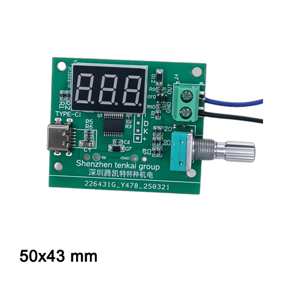
PWM generator
✅ BLDC blower / brushless fan speed control
✅ DC motor speed regulation
✅ LED brightness dimming
✅ Solenoid valve drive
✅ Circuit experiment & prototype debugging
✅ Industrial automation equipment testing
Request a Sample
Precision PWM Generators: Applications, Solutions & Industry Guide
In modern electronic engineering and industrial automation, the PWM Generator (Pulse Width Modulation Generator) serves as a fundamental control tool for precision speed regulation, signal testing, and automated power management. By modulating the duty cycle and frequency of square-wave digital signals, PWM generators deliver predictable control without requiring complex programming microcontrollers or custom hardware setups.
Key Application Fields of PWM Signal Generators
High-performance PWM generators are widely integrated across testing laboratories, production lines, and OEM equipment across multiple industries:
- BLDC & DC Cooling Fan Speed Control: Used in thermal management setups to test, calibrate, and regulate 4-wire PWM cooling fans across server racks, HVAC ventilation units, and industrial blowers.
- Brushless Motor Drivers & Electronic Speed Controllers (ESC): Delivers steady speed signals to motor drivers operating medical respiratory blowers, automated pumps, and robotics systems.
- LED Dimming & Lighting Controls: Provides flicker-free brightness modulation for high-power LED arrays, automotive lighting modules, and backlight display panels.
- Power Electronics & Switch-Mode Power Supply (SMPS) Testing: Generates driving signals for switching power circuits, DC-DC buck/boost converters, and MOSFET/IGBT gate drivers.
- Automotive & Industrial Actuator Testing: Simulates pulse control signals to test electronic throttle valves, proportional solenoids, and stepper motor positioners.
Customer Pain Points & How Precision PWM Generators Solve Them
1. Signal Distortion & Cable Attenuation
Pain Point: Standard signal sources often suffer from voltage drops, edge rounding, and high electromagnetic noise over long wires.
Solution: TKFAN PWM generators feature integrated low-impedance output buffers that preserve sharp rise/fall square-wave edges and output stability even in noisy industrial environments.
2. Inaccurate Duty Cycle & Low Frequency Steps
Pain Point: Coarse frequency tuning causes fan resonance or unstable motor rotation at specific RPM bands.
Solution: High-resolution digital tuning provides ultra-fine step adjustments (up to 0.1% duty cycle precision), eliminating motor hunting and enabling linear speed response curves.
3. Setup Complexity on Production Lines
Pain Point: Setting up computers or programming microcontrollers (MCU/PLC) for routine bench testing slows down quality assurance.
Solution: Standalone PWM signal modules provide instant plug-and-play adjustment via intuitive knobs/buttons and real-time LCD panels without writing any code.
4. Risk of Parameter Loss During Power Loss
Pain Point: Power disconnections reset test parameters, leading to configuration errors during mass testing.
Solution: Non-volatile EEPROM memory automatically saves last-used frequency and duty cycle parameters, guaranteeing consistency after every reboot.
PWM Generator - Frequently Asked Questions (FAQ)
Get expert technical answers regarding frequency selection, duty cycle scaling, wiring guidelines, and custom OEM options.
Q1: What is the main function of a PWM generator in motor and fan control?
A PWM generator outputs a digital square-wave signal with configurable frequency and duty cycle. It acts as an external signal controller to adjust motor speed, calibrate fan response curves, or test driver boards without requiring microcontrollers or PLC programming.
Q2: How does the duty cycle setting directly affect fan or motor speed?
Duty cycle represents the ratio of "ON" time versus the total period of a signal cycle. In standard 4-wire fans and BLDC drivers, a higher duty cycle (e.g., 90%) signals maximum rotational speed, whereas a lower duty cycle (e.g., 10%–20%) reduces speed or triggers standby mode depending on driver logic.
Q3: What PWM frequency setting is recommended for 4-wire DC cooling fans?
Per the standard Intel 4-wire PWM fan specification, the ideal control frequency is 25 kHz (acceptable range: 21 kHz to 28 kHz). Operating at 25 kHz prevents audible high-frequency coil humming during motor switching.
Q4: What signal voltage amplitude does the PWM generator output?
Depending on the module design, output amplitude can either be a fixed 5V TTL level or equal to the input power supply voltage (VCC, e.g., 3.3V–30V). Most standard fan control circuits and motor drivers readily accept 3.3V to 5V logic PWM inputs.
Q5: Can a single PWM generator drive multiple fans or drivers simultaneously?
Yes. Because a PWM signal is a low-power digital command (not the primary load power source), a single generator output can be connected in parallel to multiple fan or driver control pins, provided total sink current stays within the generator channel capacity.
Q6: How do I properly wire a 4-wire fan to a PWM signal generator?
Connect the main power wires (+VDC and GND) of the fan to your primary power supply. Connect the fan’s PWM input wire to the generator's PWM output terminal. Always ensure the ground (GND) wire of the PWM generator is tied to the main power supply GND for a common reference point.
Q7: What is the key difference between frequency (Hz) and duty cycle (%)?
Frequency (measured in Hz or kHz) dictates how many signal cycles occur per second, setting the operational switching speed. Duty cycle (expressed in %) specifies the width of the active pulse within each cycle, serving as the actual speed control value.
Q8: Do TKFAN PWM generators retain settings after a sudden power loss?
Yes. All TKFAN digital PWM signal generators include built-in EEPROM non-volatile memory. Selected duty cycles and frequencies are stored automatically and restored immediately upon re-powering.
Q9: What is the operating voltage range required to power the PWM generator module?
Our standard PWM generator boards support a wide input operating range of DC 3.3V to 30V, allowing flexible integration with standard 5V, 12V, or 24V power rails across test systems.
Q10: Can TKFAN customize PWM generators for specific OEM/ODM equipment?
Yes. We offer complete OEM/ODM customization services including custom PCB geometry, panel-mount bezels, custom output signal voltage levels, dedicated enclosure designs, and pre-programmed default factory frequencies.
PWM Generator Video Demonstration
Watch our video demonstration to see how our 5V 25kHz standard PWM generator accurately controls fan speed, providing reliable performance for testing and calibration setups.
GET A QUOTE
Looking for different sizes or specifications?
Explore our full range of Accessories-PWM generator, or choose from similar models below.
Accessories-PWM generator
Need a Custom Modification?
We can customize voltage (5V/12V), wire length, and connectors. Prototypes ready in 48 hours.
Contact Our Engineers