


Quick Navigation (Step 1 - 11):
How to customize air blower with TKFAN? What is the customization process like?
When existing product specifications cannot meet customer requirements, TKFAN can accept the design and development of customized products. Based on the requirements proposed by customers, we will carry out design and customization. Looking for our standard products? Please explore our full range of Air Blower Products and Cooling Fan Products here.
CHAPT 01 — Specification Requirements
First, you need to provide the approximate dimensions of the fan, flow rate requirements, pressure or corresponding operating point requirements, noise requirements, and electrical control requirements. In the initial stage, the primary focus is on providing approximate dimensions, flow rate, and operating point requirements.
CHAPT 02 — Evaluation and Quotation
Based on your general requirements, TKFAN will propose a solution promptly, leveraging our years of research, development, and manufacturing experience. In the context of industrial fan customization, mold development and design fees are often required. TKFAN typically includes the mold and design fees directly in the proposed solution.
CHAPT 03 — Payment of Fees
If you accept TKFAN's quotation terms, you can directly pay the fees stated in the quotation. The payment terms can be flexible, such as an advance payment of 10%, 50%, or 100%. The specific details of this business collaboration can be discussed further, and the final terms will be based on the mutually agreed-upon agreement.
CHAPT 04 — Fluid Simulation
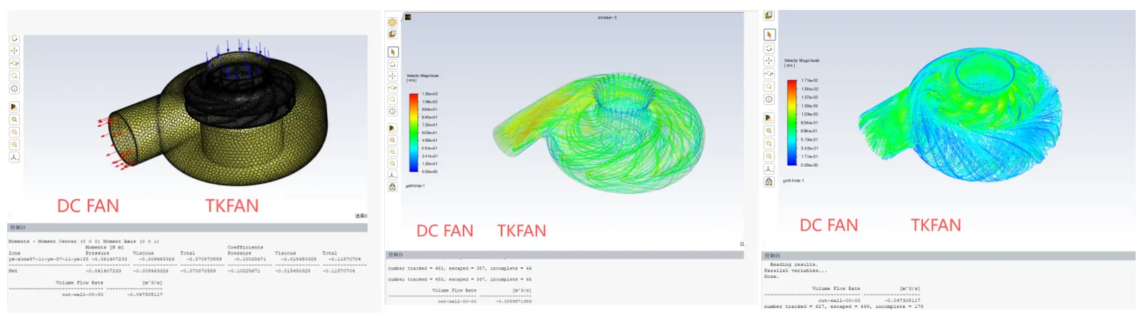
Based on your dimensional requirements, TKFAN will design fluid structures such as the fan housing, impeller, or blades within the specified dimensions, and then perform fluid simulations at specific speeds. We have highly experienced fluid engineers proficient in using Fluent, combined with supercomputing centers, to quickly obtain flow calculation results.
CHAPT 05 — Structural Modification and Fluid Simulation
Based on the simulation results of the initial version, the flow rate often fails to meet the customization specifications. When standard components fall short, a blower custom structure design becomes necessary. TKFAN will modify the housing structure, blade structure, and flow channel structure according to the actual calculation results, followed by fluid simulation, further structural modifications, and additional fluid simulation iterations until the simulation results exceed the customization specifications. In this process, we obtain two critical parameters: the fan speed and torque requirements. These parameters will be used for subsequent electromagnetic simulation calculations of the motor.
CHAPT 06 — Pressure Simulation
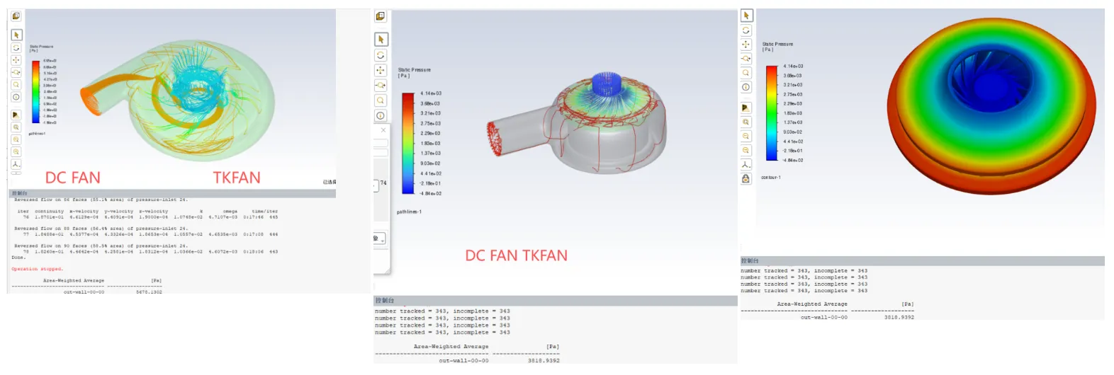
Based on the previously designed product structure, we proceed with pressure simulation for a sealed outlet. The modeling for pressure simulation differs from that of fluid simulation. During pressure simulation, we obtain another key parameter: the pressure value.
CHAPT 07 — Magnetic Circuit Simulation
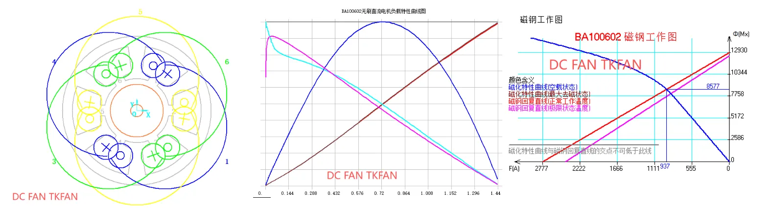
Once we obtain the rotational speed and torque data, we can proceed with the motor design and magnetic circuit simulation. Initially, we need to determine whether there are existing motors with similar dimensions that can be matched, or if a new motor design is required. Based on the requirements and through software analysis, we will ultimately determine the dimensions of the motor's stator and rotor as well as the winding parameters.
CHAPT 08 — Prototype Production
Based on the stator and rotor dimensions and winding parameters obtained from Step 7, we can manufacture motor samples using CNC housings. Using the impeller and housing drawings finalized in Step 6, physical samples of the impeller and housing can be produced via 3D printing or CNC machining.
CHAPT 09 — Assembly, Validation, and Testing
Using the prototypes obtained in Step 8, we need to validate the design prototype through testing equipment. If the validation results do not align with the design data, a redesign process is initiated: if flow rate data does not match, we return to Step 4 to restart the design; if motor data does not match, we return to Step 7 to redesign the motor.
Phase 9.1 — Flow Rate and Pressure Validation
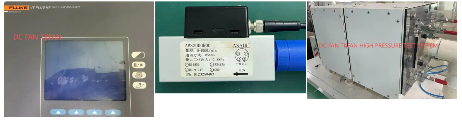
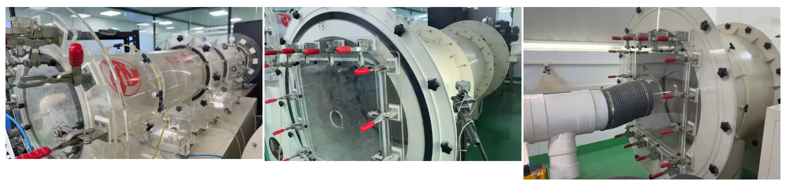
TKFAN possesses a relatively comprehensive wind tunnel testing setup with clearly defined measurement ranges. We have Fluke flow measurement equipment capable of testing minute flow rates, high-pressure wind tunnel equipment for testing up to 100,000 Pa, and large-capacity wind tunnel equipment for testing up to 2,000 CFM.
Phase 9.2 — Noise Verification
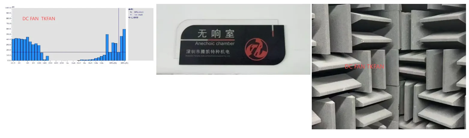
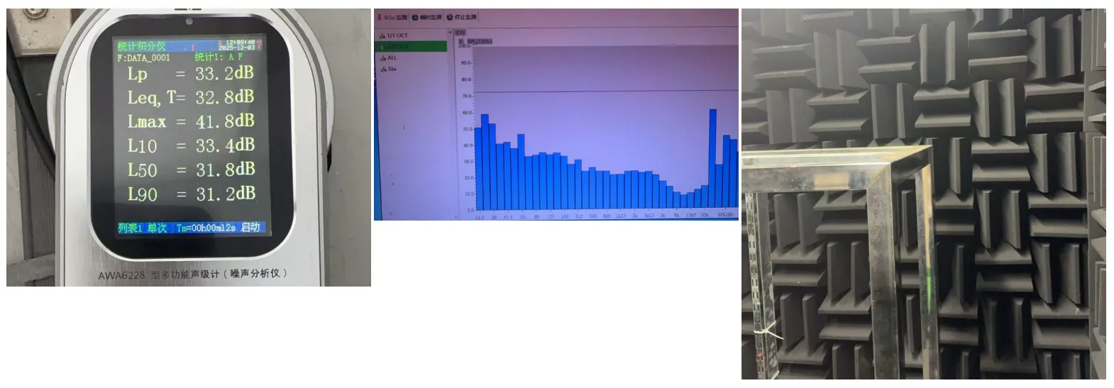
DC FAN has a dedicated noise testing chamber, where the background noise can be as low as 17dB, fully meeting the noise testing requirements for most products.
CHAPT 10 — Electrical Control Testing
Once the dimensions, flow rate, pressure, and noise levels meet the customer's requirements, TKFAN will proceed with electrical control design and compliance testing.
Phase 10.1 — Efficiency Testing
The electrical efficiency of the product must meet specific requirements, such as 90%. Excessive power consumption should not be wasted on ineffective heat generation. Higher efficiency also indicates lower temperature rise and longer product lifespan.
Phase 10.2 — Voltage Endurance Testing
Different usage scenarios require different voltage ranges. For example, household handheld products may only require a constant 5V, while automotive products may need to operate normally within 9–16V. Reliability testing in this area will be conducted according to the customer‘s specified requirements.
Phase 10.3 — Temperature Endurance Testing
Every product has an operational ambient temperature range. Some products require a range of -10°C to 50°C, others -40°C to 85°C, and some -40°C to 100°C. Based on the specific temperature requirements, temperature testing will be conducted to obtain data on motor temperature rise and the reliability of other components under extreme temperatures.
Phase 10.4 — Lifespan Testing
The product will undergo cyclic on-off testing and temperature-accelerated aging tests to preliminarily assess its expected lifespan.
Phase 10.5 — Salt Spray Testing
For customers in environments with high humidity or corrosion, salt spray testing can be added.
CHAPT 11 — Sample Delivery and Mold Production
After completing all tests, the samples are delivered to the customer. Once the customer confirms that there are no issues, mold quotation and production can proceed, moving into the manufacturing phase. 💡 Note: If you find that custom tooling takes too long, you can also check our ready-to-ship catalog on the Air Blower specification page to see if any off-the-shelf models match your data points.
Ready to Start Your Blower Custom Project?
Click below to submit your specification requirements and get a professional engineering evaluation.
GET A QUOTE
Table of Contents
Latest Post

What are external-rotor motors and internal-rotor motors, and what are the differences between them?
14 September, 2026

The Critical Role of Blower Sealing Performance in PAPR, Particle Counter, and CPAP Medical Systems
14 August, 2026
Air Particle Counter Solutions: Working Principles, Brands & Architecture
25 July, 2026