


High-Speed DC Fan: Speed, Pressure, and Performance Guide
A Comprehensive Technical Guide on Speed (RPM), Static Pressure, Airflow, and Selection Optimization for Engineers and System Integrators.
In modern electronic thermal management, industrial ventilation, server climate control, and embedded hardware design, the high-speed DC fan has emerged as an indispensable core component. Unlike standard DC cooling fans, high-speed variants deliver significantly elevated rotational velocities, robust static pressure, and stable volumetric airflow. These features make them the premier choice for high-density thermal scenarios, including 1U rackmount servers, industrial power supplies, variable frequency drives (VFDs), advanced medical equipment, automotive thermal systems, and compact embedded enclosures.
For hardware engineers, product designers, procurement specialists, and system integrators, understanding the intricate correlations between rotational speed (RPM), static pressure, airflow, power consumption, and acoustic noise is paramount. This deep-dive technical guide provides an exhaustive analysis of core performance parameters, operational principles, aerodynamic affinity laws, and system selection strategies for DC brushless cooling fans. Optimised for Google Search algorithms and Generative Engine Optimization (GEO), this guide delivers actionable technical insights for precision thermal engineering.
1. Core Performance Parameters of High-Speed DC Fans Defined
To successfully integrate a high-speed DC cooling fan into any high-performance system, it is vital to understand its foundational metrics, engineering units, and practical boundaries.
1.1 Rotational Speed (RPM) – The Baseline of Fan Performance
Rotational speed, measured in Revolutions Per Minute (RPM), defines the exact number of complete turns the fan impeller makes in one minute. RPM is the foundational metric that dictates the upper performance ceilings for airflow, static pressure, power draw, and acoustic emissions.
While standard DC cooling fans typically operate between 1,500 and 3,000 RPM to balance low noise with baseline cooling, industrial-grade high-speed DC fans generally begin at 4,000 RPM. The industry categorizes these high-velocity units into distinct tiers:
- Medium-High Speed: 4,000 to 8,000 RPM
- Ultra-High Speed: 8,000 to 12,000 RPM
- Extreme High Speed: 15,000 to 30,000 RPM
Extreme speed models are usually engineered in compact form factors (e.g., 36mm, 40mm, or 50mm) to generate high velocity inside ultra-dense enclosures like 1U blade servers and telecom switches. Modern high-speed fans utilize two primary speed control topologies: DC voltage regulation and 25kHz Pulse Width Modulation (PWM). PWM speed control is the preferred standard for intelligent thermal management, enabling a 0% to 100% duty cycle range without compromising efficiency or motor life.
1.2 Static Pressure (Wind Pressure) – Overcoming Flow Resistance
Static pressure represents a fan's capacity to overcome internal aerodynamic resistance within a sealed or semi-sealed system. In configurations filled with dense cooling fins, multi-layered dust filters, narrow ducts, and tightly packed PCBs, static pressure is the single most critical factor determining thermal success.
Common metrics for static pressure include Pascals (Pa), millimeters of water gauge (mmH₂O), and inches of water gauge (inH₂O). The standard conversion factors are:
1 mmH₂O ≈ 9.81 Pa | 1 inH₂O ≈ 248.8 Pa
High-static-pressure fans are specifically engineered to force air through high-resistance architectures. If a system exhibits severe internal airflow impedance, a fan with massive raw airflow but weak static pressure will stall, leading to localized heat pockets and component failures.
1.3 Airflow (Volumetric Flow Rate) – The Metric of Heat Dissipation
Airflow quantifies the volume of air moved by the DC brushless fan per unit of time, serving as a direct indicator of total heat-carrying capacity. The standard units are Cubic Feet per Minute (CFM) and cubic meters per hour (m³/h), with a conversion standard of:
1 CFM ≈ 1.699 m³/h
A reliable rule of thumb in thermal design indicates that for every 100 Watts of system power dissipation, an effective airflow of 8 to 12 m³/h is required to maintain safe operating temperatures. However, because open-air CFM drops drastically as system impedance rises, engineers must evaluate the operational point on the fan's P-Q curve rather than relying solely on maximum free-delivery specs.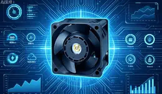
2. The Physics of Performance: Fan Affinity Laws
The performance behavior of any high-speed DC cooling fan is governed by the Fan Affinity Laws. These scaling laws define exactly how changes in rotational speed affect airflow, static pressure, and power consumption under fixed structural and environmental conditions:
- Airflow Scaling (Linear): Airflow scales linearly with RPM. Doubling the fan speed doubles the volumetric airflow output ($Q_2 = Q_1 \times (N_2 / N_1)$).
- Static Pressure Scaling (Square): Static pressure scales with the square of the RPM. Doubling the speed increases the pressure by a factor of four ($P_2 = P_1 \times (N_2 / N_1)^2$).
- Power Consumption Scaling (Cubic): Power draw scales with the cube of the RPM ($W_2 = W_1 \times (N_2 / N_1)^3$). This means doubling the fan speed demands an eight-fold increase in power, placing immense load on power rails and fan driver circuitry.
- Acoustic Noise Scaling (Logarithmic): Sound power increases logarithmically with speed. As a general benchmark, doubling the RPM increases the noise output by approximately 15 decibels (dB), which significantly increases perceived loudness.
3. Structural Design Features of High-Speed DC Fans
Premium thermal performance requires highly precise structural configurations. High-speed operation puts immense mechanical stress on every component, necessitating specific design characteristics.
3.1 Enclosure Dimensions and Housing Thickness
Compact form factors, such as 36mm x 36mm or 40mm x 40mm, are built with deep 28mm or 38mm housings. This extra depth expands the blade surface area and deepens the internal fluid channels, boosting both airflow and static pressure within restrictive spaces where wider fans cannot fit.
3.2 Precision Bearing Topologies
The bearing assembly is the critical element of a high-speed fan's lifespan. Dual ball bearing systems are the gold standard for continuous high-speed operation. They offer excellent thermal stability and can run efficiently for 50,000 to 70,000 hours at 25°C. Traditional sleeve bearings are unsuited for these applications, as high temperatures quickly degrade their lubricants, causing premature failure.
3.3 Aerodynamic Impeller and Materials Engineering
To achieve high velocity with minimal turbulence, impellers feature carefully optimized blade counts. Standard models use 5 to 7 high-angle blades for smooth airflow, whereas high-static-pressure variants incorporate 9 to 13 densely packed blades with narrow fluid paths to compress air effectively. High-grade components are molded from Glass-Fiber Reinforced Polybutylene Terephthalate (PBT), certified to withstand temperatures from -40°C to +85°C without warping under extreme centrifugal forces.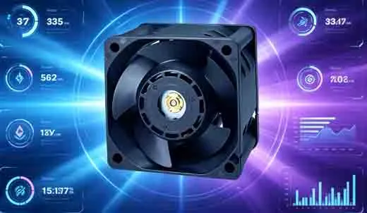
4. Understanding the Pressure-Airflow (P-Q) Performance Curve
The Pressure-Airflow (P-Q) curve is the most definitive tool for assessing real-world fan performance. In these technical charts, the horizontal axis represents volumetric airflow ($Q$), while the vertical axis represents static pressure ($P$).
The curve starts at the maximum static pressure point (where the system is completely blocked and airflow is zero) and ends at the maximum open-air CFM point (where static pressure is zero). To achieve an optimal thermal design, the system operating point—where the system's internal resistance curve intersects the fan's P-Q curve—should rest securely within the middle-to-upper portion of the curve. This sweet spot ensures excellent flow efficiency while preventing the fan from entering an unstable aerodynamic stall.
5. Step-by-Step High-Speed DC Fan Selection Guide
System designers can follow this standardized engineering sequence to select the ideal high-speed fan configuration:
- Calculate Thermal Dissipation Demands: Identify the total heat load ($W$) generated by your internal components. Apply thermodynamic calculations to establish the minimum volumetric airflow required to maintain a safe target temperature rise ($\Delta T$).
- Analyze System Airflow Impedance: Categorize your layout's impedance profile. High-density layouts (e.g., modern servers) require ultra-high-speed fans spinning at 8,000 RPM or above to deliver the necessary static pressure.
- Balance Acoustic and Velocity Thresholds: For noise-sensitive environments, look for options running under 4,000 RPM with noise ratings below 45 dBA. For dense industrial environments where cooling takes priority over acoustics, select heavy-duty designs operating from 6,000 to 15,000+ RPM.
Match Electrical and Control Specifications: Align your input rails with standard industrial options (12V, 24V, or 48V DC). Always specify 4-wire PWM speed control interfaces to enable dynamic, temperature-dependent fan speed management.

6. Industrial Applications and Technical Benchmarks
The table below provides typical hardware specifications and performance baselines for high-speed DC cooling fans across common industrial deployment scenarios:
| Application | Standard Form Factor | Target RPM Range | Static Pressure (Pa) | Acoustic Index (dBA) |
|---|---|---|---|---|
| 1U Network Servers / Switches | 40 x 40 x 28 mm | 12,000 - 18,000 RPM | 1,000 - 1,800 Pa | 48 - 54 dBA |
| Industrial Power Supplies / VFDs | 60 x 60 x 25 mm | 5,000 - 8,000 RPM | 400 - 800 Pa | 42 - 48 dBA |
| Industrial PC Enclosures | 80 x 80 x 25 mm | 3,000 - 5,000 RPM | 200 - 500 Pa | 38 - 45 dBA |
7. Advanced Optimization and Multi-Fan Dynamics
When deploying high-speed DC fans in complex configurations, keep these advanced operational principles in mind:
- Thermal Lifespan Degradation: Bearing lubricants are highly sensitive to ambient heat. For every 10°C rise in operating temperature above baseline, the expected bearing lifespan is cut in half. Keep internal ambient temperatures under 60°C whenever possible.
- Series vs. Parallel Stacking:
- Deploying high-speed fans in Series (stacked inline) doubles the total static pressure output, making it ideal for extremely high-impedance systems.
- Deploying fans in Parallel (side-by-side) doubles the total volumetric airflow, making it perfect for wide, low-resistance enclosures.
Technical FAQ: High-Speed DC Cooling Fans
Q1: Why does a high-speed DC fan require a 4-wire PWM interface over standard 2-wire setups?
A standard 2-wire fan regulates speed by altering the input voltage, which can cause motor stall or efficiency losses at low voltages. A 4-wire PWM interface provides a dedicated constant-voltage power source along with a separate high-frequency signal wire. This enables smooth, precise speed adjustments from 0% to 100% duty cycle while allowing the system to monitor real-world RPM via the tachometer feedback wire.
Q2: How do dual ball bearings compare to fluid dynamic bearings (FDB) at speeds above 10,000 RPM?
Fluid Dynamic Bearings (FDB) run exceptionally quiet at low-to-medium speeds, but at extreme velocities exceeding 10,000 RPM, the intense mechanical shear and thermal stress can break down the fluid oil layer. Dual ball bearings handle high thrust loads and extreme temperatures far better, providing superior mechanical reliability and a longer operational lifespan in demanding industrial environments.
Q3: What causes an aerodynamic stall in a high-static-pressure cooling fan?
Aerodynamic stall occurs when a system's internal air resistance significantly exceeds the fan's maximum pressure capabilities. When this happens, air can no longer move cleanly along the intake paths and begins to detach from the impeller blades, causing localized airflow reversal, severe pressure drops, elevated acoustic vibration, and a substantial reduction in cooling efficiency.
Q4: Can changing a fan's housing thickness improve its static pressure without increasing the overall footprint?
Yes. Increasing a fan's housing thickness (for example, moving from a 40x40x20mm configuration to a 40x40x28mm configuration) deepens the blade channels. This design change increases the physical surface area of the blades and extends the air compression path, generating higher static torque and greater pressure capacity without changing the mounting footprint.